Current drive, Encoder, Current source – Yaskawa SMC–4000 User Manual
Page 32: Velocity loop
22
SMC–4000 User Manual
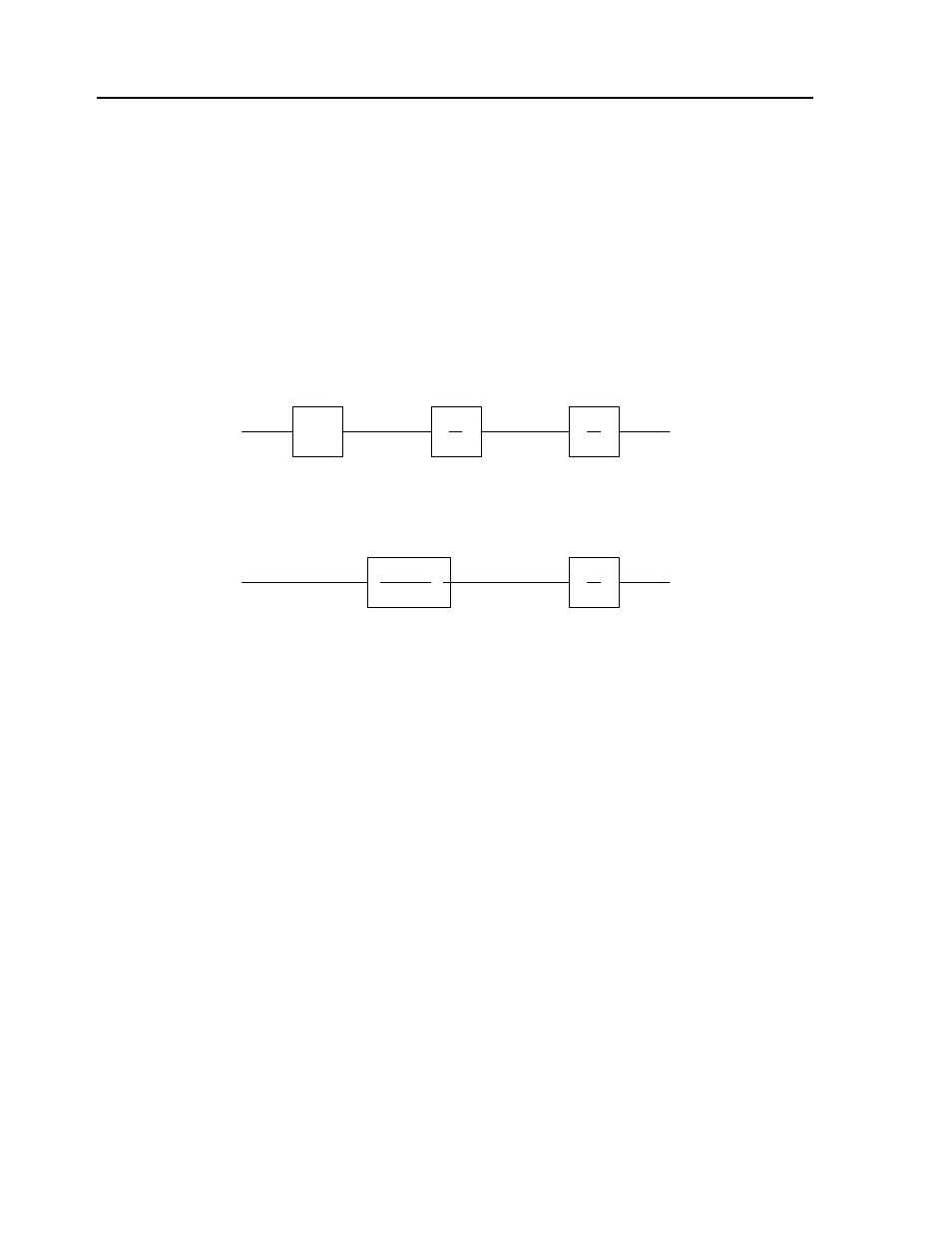
Current Drive
The current drive generates a current I, which is proportional to the input voltage, V, with a gain of Ka, a
torque constant of K
t
, and inertia J. The resulting transfer function in this case is:
P/V = K
a
K
t
/ Js
2
For example, a current amplifier with K
a
= 2 A/V with the motor described by the previous example will
have the transfer function:
P/V = 1000/s
2
[rad/V]
Mathematical model of the motor and amplifier in two operational modes
Encoder
The encoder generates N pulses per revolution. It outputs two signals, Channel A and B, which are in
quadrature. Due to the quadrature relationship between the encoder channels, the position resolution is
increased to 4N quadrature counts/rev.
The model of the encoder can be represented by a gain of:
K
f
= 4N/2
π [count/rad]
For example, a 1000 lines/rev encoder is modeled as:
K
f
= 638
DAC
The DAC or D-to-A converter converts a 16-bit number to an analog voltage. The input range of the
numbers is 65538and the output voltage range is +/-10V or 20V. Therefore, the effective gain of the DAC
is:
K= 20/65538 = 0.000305 [V/count]
K
a
K
t
JS
1
S
V
I
W
P
CURRENT SOURCE
1
S
V
W
P
VELOCITY LOOP
1
K
g
(ST
1
+1)