Command summary - electronic gearing, Electronic gearing – Yaskawa SMC–4000 User Manual
Page 290
280
SMC–4000 User Manual
Electronic Gearing
This mode allows any axes to be electronically geared to some master axes. The masters may rotate in
both directions and the geared axis will follow at the specified gear ratio. The gear ratio may be different
for each axis and changed during motion.
The command
ABCD specifies the master axes.
x,y
specifies the gear ratios for the slaves where the ratio may be a number between +/-127.9999 with a
fractional resolution of 0.0001. There are two modes: standard gearing and gantry mode. The gantry mode
is enabled with the command GM. GR 0,0 turns off gearing in both modes. A limit switch or
command disables gearing in the standard mode but not in the gantry mode.
The command
a,b,c,d selects the axis to be controlled under the gantry mode. The
parameter 1 enables gantry mode, and 0 disables it.
causes the specified axes to be geared to the actual position of the master. The master axis
is commanded with motion commands such as
.
When the master axis is driven by the controller in the jog mode or an independent motion mode, it is
possible to define the master as the command position of that axis, rather than the actual position. The
designation of the commanded position master is the letter, C. For example, GACA indicates that the
gearing is the commanded position of A.
An alternative gearing method is to synchronize the slave motor to the commanded vector motion of
several axes performed by GAS. For example, if the A and B motor form a circular motion, the C axis may
move in proportion to the vector move. Similarly, if A, B and C perform a linear interpolation move, W
can be geared to the vector move.
Electronic gearing allows the geared motor to perform a second independent or coordinated move in
addition to the gearing. For example, when a geared motor follows a master at a ratio of 1:1, it may be
advanced an additional distance with
, or
commands.
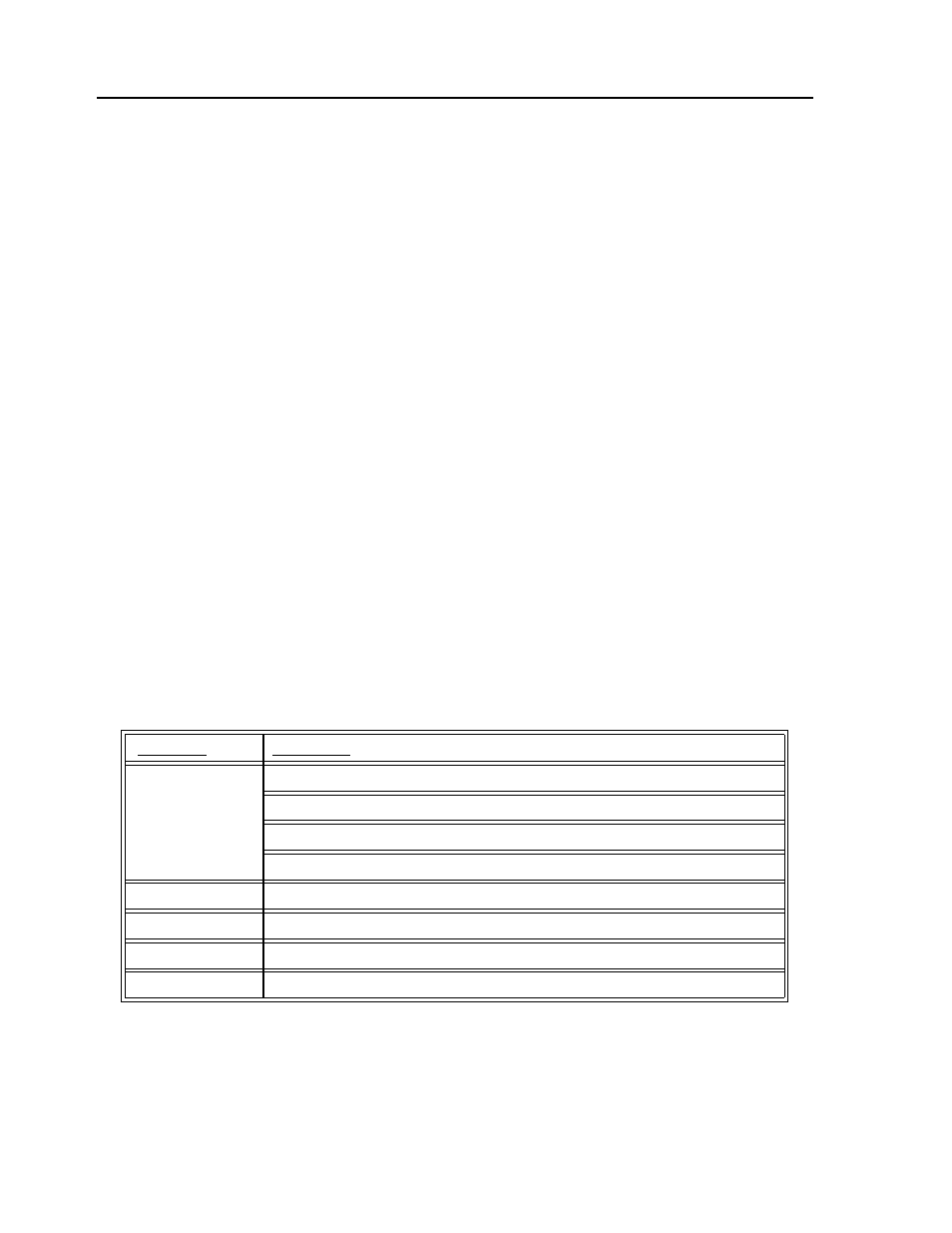
Command Summary - Electronic Gearing
Command
Description
GA n
Specifies master axes for gearing where n=A,B,C,D for main encoder as master.
n=CA,CB,CC,CD for commanded position.
n=DA,DB,DC,DD for auxiliary encoders.
n=S or T for gearing to coordinated motion.
GR a,b,c,d
Sets gear ratio for slave axes. 0 disables electronic gearing for specified axis.
GM a,b,c,d
1 sets gantry mode, 0 disables gantry mode.
MR a,b,c,d
Trippoint for reverse motion past specified value. Only one field may be used.
MF a,b,c,d
Trippoint for forward motion past specified value. Only one field may be used.