Mitsubishi fx series plc via computer link, Fx series computer link – Delta Electronics Network Device DOP-A/AE/AS User Manual
Page 87
Delta DOP Series HMI Connection Manual|DOP-A/AE/AS Series
1-86
Revision January, 2008, Doc. Name: 2007PDD23000007
Mitsubishi FX Series PLC via Computer Link
A. HMI factory settings
Baud rate: 9600, 7, EVEN, 1.
Controller Station number: 0.
Control area/status area: D0 / D10.
NOTE
1) This communication protocol supports FX series RS485 and RS232 communication module.
2) The default setting of this communication protocol is to support RS485 communication module. If the
user needs to use RS232 communication module, the user must change the communication setting from
RS485 to RS232 manually.
3) For more detailed information regarding the communication setting method, please refer to Mitsubishi
Communication User Manual named “User’s Manual - Data Communication Edition”.
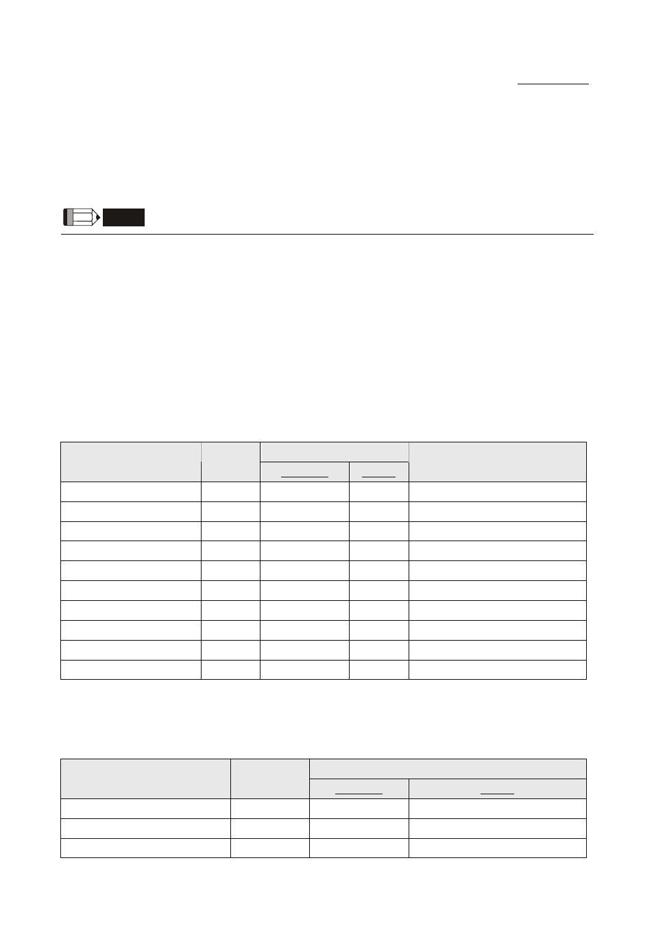
B. Definition of controller Read/Write address
Registers
Read/Write Range
Register Type
Format
Word No.
Bit No.
Data length
Auxiliary Relay
Mn
n: 0-7679
N/A
Word
Special Auxiliary Relay
Mn
n: 8000-8511
N/A
Word
Status Relay
Sn
n: 0-4095
N/A
Word
Input Relay
Xn
n: 0-377(octal)
N/A
Word
Output Relay
Yn
n: 0-377(octal)
N/A
Word
Timer PV
Tn
n: 0-255
N/A
Word
16-bit Counter PV
Cn
n: 0-199
N/A
Word
32-bit Counter PV
Cn
n: 200-255
N/A
Double Word
Data Register
Dn
n: 0-7999
N/A
Word
Special Data Register
Dn
n: 8000-8511
N/A
Word
¾
Auxiliary Relay / Special Auxiliary Relay / Status Relay / Input Relay / Output Relay: Address must be
the multiple of 16.
Contacts
Read/Write Range
Contact type
Format
Word No.
Bit No.
Auxiliary Relay
Mn
N/A
n: 0-7679
Special Auxiliary Relay
Mn
N/A
n: 8000-8511
Status Relay
Sn
N/A
n: 0-4095