Delta Electronics Network Device DOP-A/AE/AS User Manual
Page 42
Delta DOP Series HMI Connection Manual|DOP-A/AE/AS Series
Revision January, 2008, Doc. Name: 2007PDD23000007
1-41
if the read/write address format is set to Rn, only Bit 0 ~ 23 are valid for Rn registers.
(Notice: As the Jetter controller is a 24-bit format controller, the valid setting range is 24 Bits.
If exceeds this range, HMI will stop read/write operation and show “…..Value is Incorrect”
on the screen. So, please do not set any bit on Bit24 ~ Bit31 (Bit24 ~ Bit31 cannot be written).
y
When using devices that the data length is in m Words,
if the read/write address format is set to WRn, the Bit 0 ~ 15 of WRn register is the lowest word of a
read/write value and the Bit 0 ~ 15 of WRn+m-1 register is the highest word of a read/write value.
if the read/write address format is set to Rn, the Bit 0 ~ 23 of Rn register is the lowest word of a
read/write value and the Bit 0 ~ 23 of Rn+1 register is the highest word of a read/write value.
Each register is regards as a “Double Word”. The value of Bit24 ~ Bit31 is 0.
Contacts
Read/Write Range
Contact type
Format
Word No.
Bit No.
Input Relay
Inbb
n: 1 ~ 32
bb:
01 ~ 08
Output Relay
Onbb
n: 1 ~ 32
bb:
01 ~ 08
Flag Relay
Fn
N/A
n:
0 ~ 32767
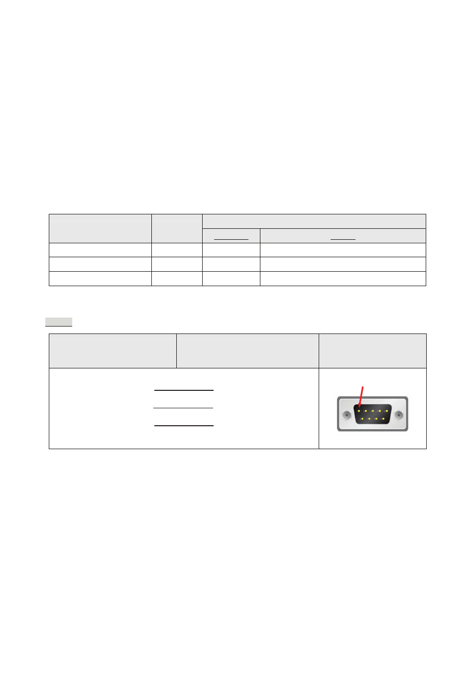
C. Connections (Connector Pinouts)
RS-232
DOP Series
9 pin D-SUB male (RS-232)
Controller
9 pin D-SUB male (RS-232)
Controller
9 pin D-SUB male
(RS-232)
RXD (2)
(2) TXD
TXD (3)
GND (5)
(3) RXD
(7) GND
Top View
¾
The pin definition of the cable of Jetter controller is different than the general RS-232 cable. Please pay
close attention.
Pin1