Jetter jc series plc, Jc series plc – Delta Electronics Network Device DOP-A/AE/AS User Manual
Page 43
Delta DOP Series HMI Connection Manual|DOP-A/AE/AS Series
1-42
Revision January, 2008, Doc. Name: 2007PDD23000007
Jetter JC Series PLC
A. HMI factory settings
Baud rate: 9600, 8, EVEN, 1 (RS-232).
Controller station number: 0. (no PLC station number in protocol, therefore, only 1(HMI) to 1 (PLC)
communication is allowed.)
Control area/status area: WR0 / WR10.
NOTE
1) Please notice that no PLC station number in protocol, therefore, only 1(HMI) to 1 (PLC) communication
is allowed.
2) Only 1 Bit or 1 Word / 2 Words can be transferred for each read and write command.
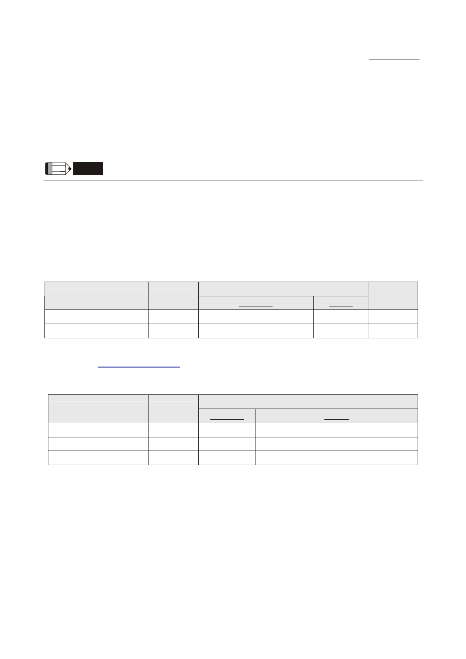
B. Definition of controller Read/Write address
Registers
Read/Write Range
Register Type
Format
Word No.
Bit No.
Data
Length
16 Bits Register
WRn
n:
0 ~ 32767
N/A
16 Bits
32 Bits Register
Rn
n:
0 ~ 32767
N/A
24 Bits
The characteristics of WRn and Rn of JC series are the same as the Nano series. Please refer to the section
that introduces
Contacts
Read/Write Range
Contact type
Format
Word No.
Bit No.
Input Relay
Inbb
n: 1 ~ 32
bb:
01 ~ 16
Output Relay
Onbb
n: 1 ~ 32
bb:
01 ~ 16
Flag Relay
Fn
N/A
n:
0 ~ 32767