2 if connections, 1 j1 tx if connectors, J3 rx if connectors – Comtech EF Data CDM-710G User Manual
Page 68: 2 j3 rx if connectors
CDM-710G High-Speed Satellite Modem
Revision 1
Rear Panel Connector Pinouts
MN-CDM710G
4–2
CA UTIO N
Table 4-1. CDM-710G Rear Panel Connectors Reference
Connector Group
Ref Des / Name
Connector Type
Function
IF
Sect. 4.2
J1 Tx
CDM-710G (70/140 MHz band):
BNC female
IF Output
CDM-710GL (L-Band):
Type ’N’ female
J3 Rx
CDM-710G (70/140 MHz band):
BNC female
IF Input
CDM-710GL (L-Band):
Type ’N’ female
Terrestrial Data
Sect. 4.3
J4 Ethernet
RJ-45 Female
10/100 BaseT Remote Interface
J6 Async Channel
(non-operational)
9-pin Type ‘D’ female
Asynchronous Engineering Channel
Utility
Sect. 4.4
P1 Alarms
15-pin Type ‘D’ male
Form C Alarms (relay closures)
P2 Remote
9-pin Type ‘D’ male
Serial Remote Interface (RS232/485)
J7 Ext Ref
BNC female
External Reference Input
Power/Ground
AC
IEC
Chassis prime power input
DC
Terminal block
Chassis prime power input
Ground
#10-32 stud
Common Chassis Ground
4.2
IF Connections
There may be DC voltages present on the Type ‘N’ Rx and Tx IF connectors, up to
a maximum of 48 volts.
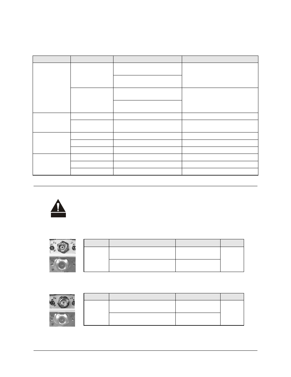
4.2.1
J1 Tx IF Connectors
Ref Des
Connector Type
Description
Direction
J1
CDM-710G (70/140 MHz band):
BNC female
70/140 MHz Tx IF
signal
Out
CDM-710GL (L-Band):
Type ’N’ female
L-Band Tx IF signal
4.2.2
J3 Rx IF Connectors
Ref Des
Connector Type
Description
Direction
J2
CDM-710G (70/140 MHz band):
BNC female
70/140 MHz Rx IF
Signal
In
CDM-710GL (L-Band):
Type ’N’ female
L-Band Rx IF Signal