4 general specifications, Continuous clock gap clock – Comtech EF Data CDM-710G User Manual
Page 178
CDM-710G High-Speed Satellite Modem
Revision 1
HSSI Interface (CDI-60)
MN-CDM710G
13–4
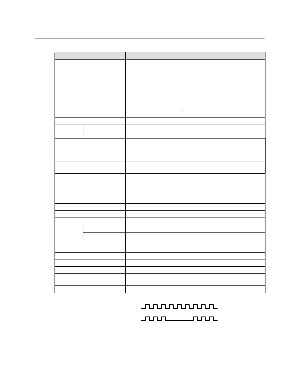
Continuous Clock
Gap Clock
13.4
General Specifications
Item
Requirement
Data Rate Range
1 to 70 Mbps
Note: HSSI data rate limit of 70 Mbps may be reached before symbol rate limit is
reached.
Interfaces Per Module
One HSSI
Signals Supported
ST, TT (or external) , SD, TA, CA, RT, RD, SG
Connector
DCE, 50-pin mini-D female per EIA-613 (HSSI)
Electrical
Per EIA-612 (10KH ECL compatible).
Electrical Typical
Differential output voltage:
> 590 mV pp into 110 load
Differential Input voltage: 150 to 1000 mV pp with 110 load
Minimum Buffer Size
5.0 mS smallest buffer setting, 0.1 mS step size, 32 mS maximum size
Impedance
Rx
110 for TT, SD, TA
Tx
ST, CA, RT, RD will drive 110 and meet HSSI voltage levels
Signal Characteristics
The A terminal is negative with respect to the B terminal for a binary 0 (Space or
OFF) state.
The A terminal is positive with respect to the B Terminal for a binary 1 (Mark or
ON) state.
Clock / Data Relationship
The data transitions occur during the OFF to ON transition of the clock. Data is
stable during the ON to Off transition of the clock.
Tx Clock Modes
TT (Input clock) continuous.
ST (output clock) is continuous output, programmable in 1 bps steps or phase
locked to satellite clock
Rx Clock Modes
RT (output clock) is continuous from satellite, ST (internal clock), continuous
from TT
Gap Clock (See Figure 13-4)
Not allowed – Send ST to external equipment so it will return a continuous clock
Tx / Rx Clock
Asymmetrical clocking with Rx Doppler buffer disabled
Acquisition Range
Programmed Tx data rate
± 100 ppm
TA / CA
Default
CA looped to TA
Selection:
CA is asserted when there is no modem fault
Test
I/O Loopback per the Appendix
Interface Loopback per the Appendix
Operation
Simplex (Tx only or Rx only) or full duplex
Signal Sense
Programmable Normal or Inverted for TT and TD, RT and RD
Modules Per Modem
The interface operates in Slot 1, Slot 2, or both slots.
Cable Length to 52 Mbps
2 m (6 ft) nominal, up to 15 m (49 ft) maximum – Note higher data rates usually
require shorter cable lengths.
LED
Green LED indicates channel is enabled
Figure 13-4. Continuous and Gap Clock at TT