2 rear panel, 5 allowable data interface combinations, 1 additional data interface information – Comtech EF Data CDM-710G User Manual
Page 34
CDM-710G High-Speed Satellite Modem
Revision 1
Introduction
MN-CDM710G
1–8
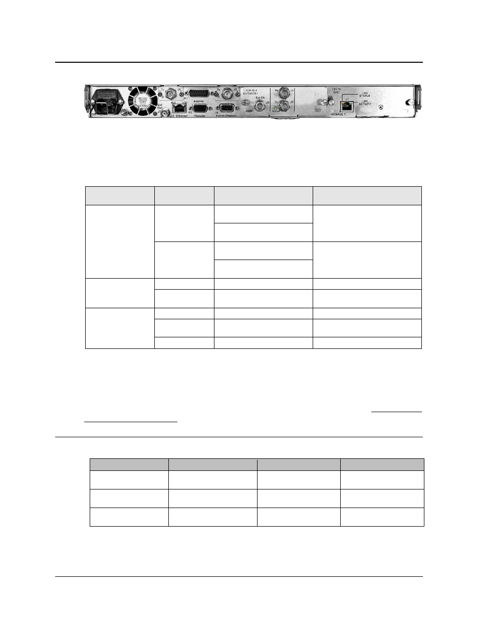
1.3.4.2 Rear Panel
Figure 1-5. Rear Panel View (shown with optional G.703 and GigE Interfaces)
Figure 1-5 shows the rear panel of the CDM-710G. External cables are attached to connectors on
the rear panel of the CDM-710G. Each connector is described in detail in Chapter 4. REAR
PANEL CONNECTOR PINOUTS. They comprise:
Connector Group
(Chapter 4 Sect. Ref.)
Ref Des / Name
Connector Type
Function
IF
(Sect 4.2)
J1 Tx
CDM-710G (70/140 MHz band):
BNC female
IF Output
CDM-710GL (L-Band):
Type ’N’ female
J3 Rx
CDM-710G (70/140 MHz band):
BNC female
IF Input
CDM-710GL (L-Band):
Type ’N’ female
Terrestrial Data
(Sect 4.3)
J4 Ethernet
RJ-45 Female
10/100 Base-T Remote Interface
J6 Async Channel
(non-operational)
9-pin Type ‘D’ female
Asynchronous Engineering Channel
Utility
(Sect 4.4)
P1 Alarms
15-pin Type ‘D’ male
Form C Alarms (relay closures)
P2 Remote
9-pin Type ‘D’ male
Serial Remote Interface
(RS232/485)
J7 Ext Ref
BNC female
External Reference Input
1.3.5
Allowable Data Interface Combinations
Data interfaces are installed or removed from the rear of the CDM-710G chassis into Slot 1 and
Slot 2 of the CDM-710G. The allowable combination of data interfaces and the data interfaces
that are supported for redundancy are found in the table below. In all cases, only one data
interface is active at a time.
1.3.5.1 Additional Data Interface Information
Interface
Number
1:1 Capability
1:N Capability
G.703 (CDI-10-1)
PL/10008-2
(Also see Chapter 12)
OK Tx, Rx or Duplex
OK Tx, Rx or Duplex
HSSI (CDI-60)
PL/11582-1
(Also see Chapter 13)
OK Tx, Rx or Duplex
OK Tx, Rx or Duplex
Gigabit Ethernet (CDI-70)
PL/11509-3
(Also see Chapter 14)
OK Tx, Rx or Duplex
OK Tx, Rx or Duplex