2 cdm-710gl l-band demodulator – Comtech EF Data CDM-710G User Manual
Page 43
CDM-710G High-Speed Satellite Modem
Revision 1
Introduction
MN-CDM710G
1–17
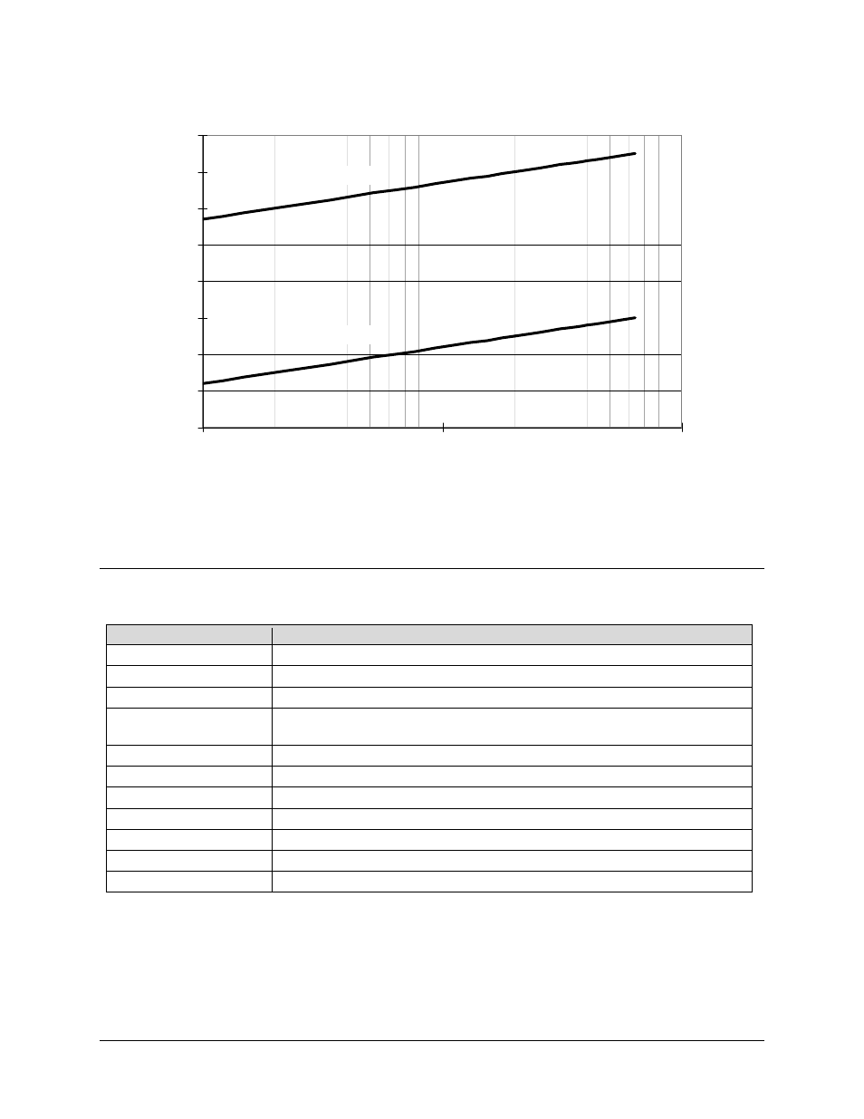
Figure 1-7. Demodulator Input Level
1.5.3.2 CDM-710GL L-Band Demodulator
Description
Requirements
Frequency Range
950 MHz to 1950 MHz in 100 Hz steps
Impedance/Connector
50
Ω/Type N Female
Return Loss
15 dB
Input Power, Minimum
-58 + 10xLog(Symbol Rate in MHz) dBm,
-58 dBm at 1 Msps, -41.5 dBm at 45 Msps
AGC Range
45 dB above minimum
Max Composite Level
+30 dBc composite to desired up to +10 dBm
Acquisition Range
± 100 kHz programmable in 1 kHz steps
Acquisition Time
Typical < 10 seconds, DVB-S2 Pilots On
Adaptive Equalizer
Up to 3 dB tilt
BER Performance
IQ Test Point
Accessible from rear panel Alarm connector
-70
-60
-50
-40
-30
-20
-10
0
10
1
10
100
Symbol Rate (Msps)
C
ar
ri
er
I
n
p
u
t L
evel
(
d
B
m
)
Maximum Level
Minimum Level
Carrier Input Level (vs) Symbol Rate