2 physical description, Gigabit ethernet card – Comtech EF Data CDM-710G User Manual
Page 182
CDM-710G High-Speed Satellite Modem
Revision 1
10/100/1000 Base-T Gigabit Ethernet (GigE) Interface (CDI-70)
MN-CDM710G
14–2
GE
Layer 2
Switch
GE
Layer 2
Switch
Packet
Processor
Packet
Processor
Modem
Interface
Clk
&
Data
μC
Gigabit Ethernet Card
J1
RJ-45
RJ-45
Management
Packet
Processor
Management
Packet
Processor
Memory
Memory
Ethernet
Interface
14.2
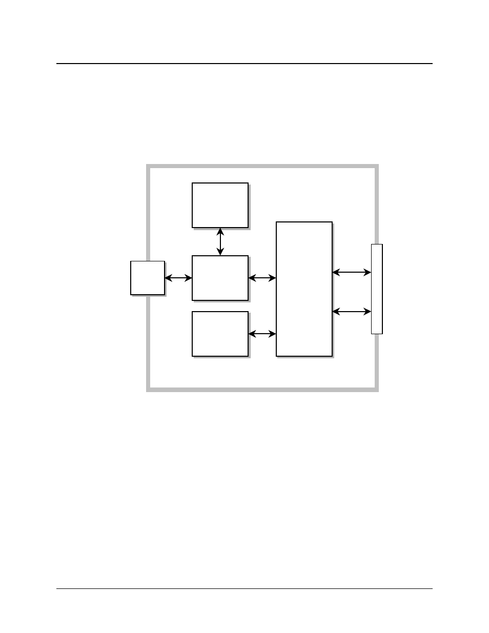
Physical Description
The CDI-70 data interface is implemented on a 3.95 x 7.022 inch (10.03 x 17.83 cm) PCB.
Connectivity to the CDM-710G is implemented with a 96-pin DIN receptacle. The LAN interface
consists of a single IEEE 802.3ab 1000 Base-T copper-compliant female RJ-45 connector – refer
to Sect. 14.3 for the connector pinout. This connector features Light-Emitting Diode (LED)
indicators for Link Status and Link Activity.
Figure 14-2 shows a block diagram for the CDI-70 interface.
Figure 14-2. CDI-70 Interface Module Block Diagram