6 verification – Comtech EF Data CDM-710G User Manual
Page 35
CDM-710G High-Speed Satellite Modem
Revision 1
Introduction
MN-CDM710G
1–9
1.3.5.2 Data Interface Support in 1:1, 1:N Redundancy Configurations
1:1 Redundancy with the CRS-180 (70/140 MHz) or CRS-170A (L-Band) Redundancy
Switch: The “CDM-710G Unit Configuration” column in Table 1-1 shows the CDM-710G
data interface combinations that are supported by the CRS-180 and CRS-170A 1:1 Redundancy
Switches. First, the 1:1 switch is selected depending upon the operating frequency, and then a
data interface kit for Slot 1 and Slot 2 is chosen. More information on these kits is provided in the
CRS-170A or CRS-180 1:1 Redundancy Switch datasheet and Installation and Operation manual.
When a CDM-710G is used as a Tx Only unit in 1:1 Redundancy, the demodulator
card must be removed. Similarly, when used as an Rx Only unit in 1:1
Redundancy, the modulator card must be removed.
1:N Redundancy with the CRS-300: The CRS-300 was originally designed for operation with the
CDM-600 and subsequently adapted to a number of other modems. It is capable of supporting
interfaces up to the point where there are no more paths left to route traffic; this is the reason why
the CRS-300 supports a limited set of the interface combinations supported by the CDM-710G.
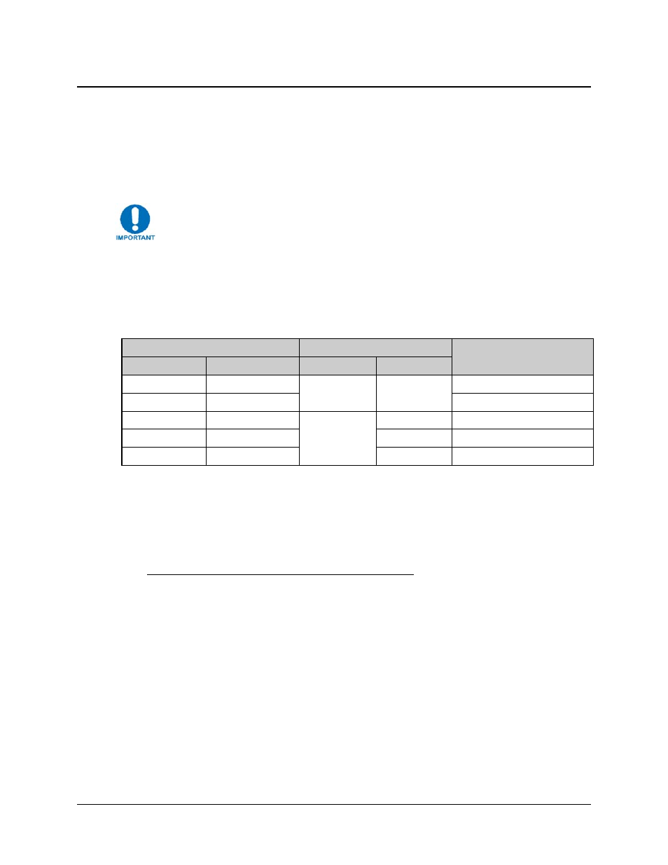
Table 1-1. Allowable Unit/Switch Data Interface Configurations
CDM-710G Unit Configuration
1:N CRS-300 Configuration
Notes
Interface Slot 1
Interface Slot 2
TMI Card
RMI Card
G.703 (CDI-10-1)
None
CRS-325 CRS-306
-
G.703 (CDI-10-1)
GigE (CDI-70)
Can be used as Redundant Unit
HSSI (CDI-60)
None
CRS-336
-
None
GigE (CDI-70)
CRS-306
-
HSSI (CDI-60)
GigE (CDI-70)
Can be used as Redundant Unit
Notes:
1. The Redundant Unit must have the same interface cards in each slot as any of the Traffic
Units.
2. The Traffic Unit must have the same interface cards in each slot as any of the other Traffic
Units have, or a blank panel installed.
3. Interface Slots 1 and 2 are not active simultaneously.
1.3.6
Verification
The unit includes a number of tests for rapid verification of the correct functioning of the unit.
Selection of a CW carrier permits measurement of carrier center frequency or phase noise
characteristic. A single-sideband carrier also is available at the operating symbol rate to check I
and Q phase and amplitude balance. When normal operation is again selected, all of the previous
values are restored.