Logic connections, Operational settings – Basler Electric BE1-11g User Manual
Page 64
52
9424200994 Rev N
If the 60FL element trip logic is true and Block Phase/V1 is enabled, all functions that use the phase
voltage are blocked. See the Fuse Loss (60FL) chapter for more information on the 60FL functions.
Protective elements blocked by 60FL should be set so that trip times are 60 milliseconds or greater to
assure proper coordination of blocking.
Block Logic Input
The Block input provides logic-supervision control of the element. When true, the Block input disables the
element by forcing the element outputs to logic 0. Connect the element Block input to the desired logic in
BESTlogicPlus. When the element is initially selected from the Elements view, the default condition of the
Block input is a logic 0.
Logic Connections
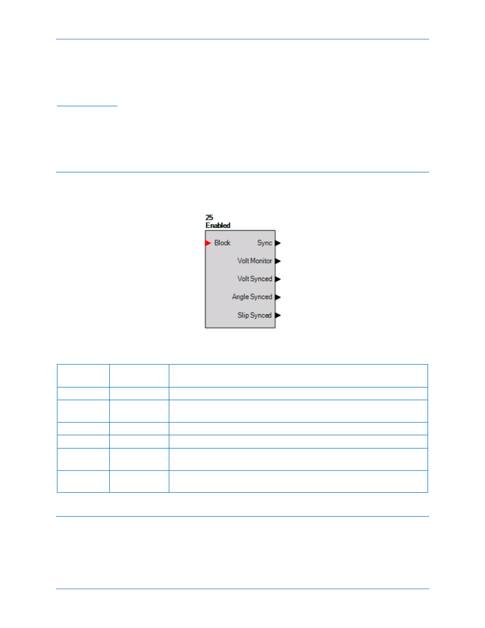
Sync-check element logic connections are made on the BESTlogicPlus screen in BESTCOMSPlus. The
sync-check element logic block is illustrated in Figure 42. Logic inputs and outputs are summarized in
Table 12.
Figure 42. Sync-Check Element Logic Block
Table 12. Logic Inputs and Outputs
Name
Logic
Function
Purpose
Block
Input
Disables the 25 function when true
Sync
Output
True when the monitored voltage between the sources meets angle,
voltage, and slip criteria
Volt Monitor
Output
True when the bus and/or line is dead
Volt Synced
Output
True when the voltage magnitude between sources is less than setting
Angle
Synced
Output
True when the phase angle between sources is less than the Slip
Angle setting
Slip Synced
Output
True when the frequency error between sources is less than the Slip
Frequency setting
Operational Settings
Sync-check element operational settings are configured on the Sync-Check (25) settings screen (Figure
43) in BESTCOMSPlus. Setting ranges and defaults are summarized in Table 13.
Sync-Check (25) Protection
BE1-11g