Programming example – Basler Electric BE1-11g User Manual
Page 30
18
9424200994 Rev N
Programming Example
Changing default logic is sometimes required to match the protection requirements of the system.
Additionally, elements must be enabled and operating settings set. This example demonstrates how to
configure typical nominal settings and program the 50-3 instantaneous overcurrent element. System
nominal quantities are set to 69.3 volts and 3.6 amps. The 50-3 element is set for a 5.62 amp pickup and
a 30 second time delay. Additionally, the element pickup output is logically wired to output 4 and a user
alarm.
Step 1: Start BESTCOMSPlus and select New Connection, BE1-11 from the Communication pull-down
menu to connect to the BE1-11g. See Figure 7.
Step 2: The BE1-11 Connection screen appears. See Figure 8. Select USB Connection and click
Connect.
Step 3: Select Download Settings and Logic from Device from the Communication pull-down menu. This
copies all settings and logic from the BE1-11g to BESTCOMSPlus.
Step 4: Click on the View drop-down button and de-select Show Metering Panel and Show Setting
Information. See Figure 10. This maximizes the workspace.
Step 5: In the Settings Explorer, click the “+” next to BE1-11. This expands the sub menus in the tree.
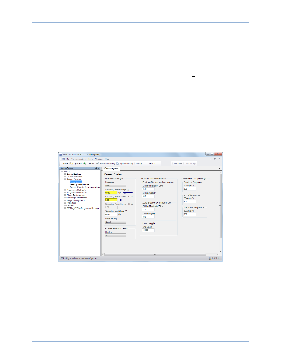
Now expand System Parameters and select the Power System screen. See Figure 12.
Step 6: Under Nominal Settings, enter settings for Secondary Phase Voltage (69.3 V) and Secondary
Phase Current (3.6 A).
Figure 12. Power System Screen
Step 7: In the Settings Explorer, expand Protection, Current and select the Instantaneous Overcurrent
(50-3) screen. See Figure 13.
Step 8: Select the Mode (3 Phase) and enter settings for Pickup (5.62 A) and Time Delay (30,000 ms).
Step 9: In the Settings Explorer, click BESTlogicPlus Programmable Logic to open the logic diagram.
Click the Logic Page 1 tab. See Figure 14. Examine the 50-3 element. The Logic 0 connected to
the Block input indicates that the 50-3 element is never blocked.
Off-Page Inputs/Outputs are used to make connections between logic pages and help keep logic
diagrams free from clutter. The Trip output is connected to an Off-Page Output named 50-3 Trip.
This 50-3 Trip Off-Page Output is carried over to the Logic Page 2 tab (Figure 15) where it
becomes an Off-Page Input. The 50-3 Trip Off-Page Input and several others are AND gated to
the Trip Bus Off-Page Output which is carried over to the Logic Page 3 tab (Figure 16) where it
Quick Start
BE1-11g