Voltage monitoring, Element blocking – Basler Electric BE1-11g User Manual
Page 63
9424200994 Rev N
51
Phase VT
Connection
Phase
Rotation
Aux VT
Connection
Secondary
Phase Voltage
(Phase-Neutral)
Secondary
Aux Voltage
Angle
Compensation
AB
ABC
AB
69.3
120
0
°
AB
ACB
AB
69.3
120
0
°
BC
ABC
BC
69.3
120
0
°
BC
ACB
BC
69.3
120
0
°
AB
ABC
BC
69.3
120
240
°
AB
ACB
BC
69.3
120
120
°
AB
ABC
AN
69.3
69.3
330
°
AB
ACB
AN
69.3
69.3
30
°
Voltage Monitoring
The sync-check element Sync logic output provides closing supervision for only the live line/live bus
condition.
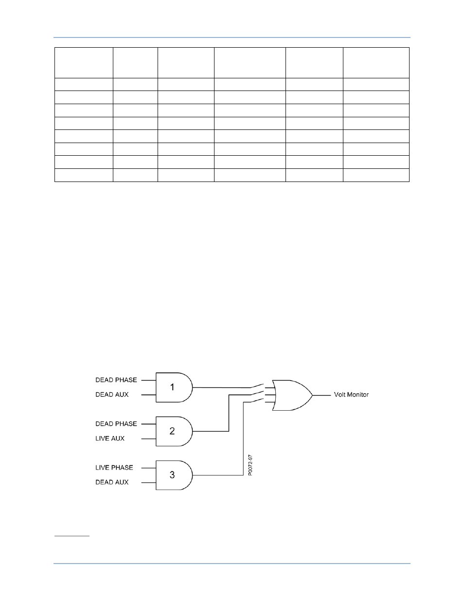
The Volt Monitor logic output is provided for conditions where the bus and/or the line are dead. In
BESTlogicPlus, the Volt Monitor logic output can be connected to other logic elements to annunciate the
condition or control other elements in logic. A live condition for either the phase voltage or auxiliary
voltage is determined when the measured voltage on the respective input is equal to or above the live
voltage threshold established by the Live Voltage setting. A dead condition for either phase voltage or
auxiliary voltage is determined when the measured voltage on the respective input is equal to or below
the dead voltage threshold established by the Dead Voltage setting. The Dropout Delay setting provides
hysteresis for the Volt Monitor logic output.
For the phase voltage input, if the connection is three phase, 3W or 4W, all three phases are tested and
must be above the live voltage threshold for a live condition to be true. Similarly, all three phases must be
below the dead voltage threshold for a dead condition to be true.
The Volt Monitor logic is illustrated in Figure 41. Any combination of logic settings can be selected for the
Voltage Monitor Logic on the Sync-Check (25) settings screen in BESTCOMSPlus. When a logic
combination is selected, the sync-check element closes the respective switch in Figure 41 associated with
each of the outputs.
Figure 41. Voltage Monitor Logic
Element Blocking
Fuse Loss
The fuse loss (60FL) element of the BE1-11g can be used to block the 25 element when fuse loss or loss
of potential is detected in a three-phase system.
BE1-11g
Sync-Check (25) Protection