N figure 24, Table 3, Figure 24 – Basler Electric BE1-11g User Manual
Page 39
9424200994 Rev N
27
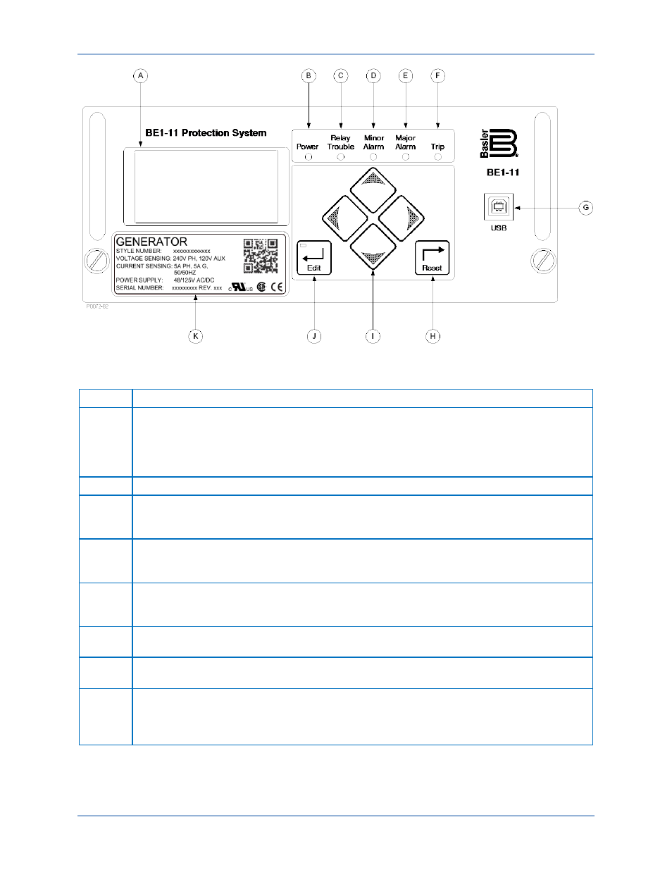
Figure 24. Front Panel (H or P Type Case)
Table 3. Front Panel Descriptions (H or P Type Case)
Locator
Description
A
Display – 64 x 128 dot pixels liquid crystal display (LCD) with backlighting. The LCD is the
primary source for obtaining information from the BE1-11g or when locally setting the
BE1-11g. Information such as targets, metering values, demand values, communication
parameters, and diagnostic information is provided by the LCD. Information and settings are
displayed in a menu.
B
Power Indicator – This green LED lights when operating power is applied to the BE1-11g.
C
Relay Trouble Indicator – This red LED lights momentarily during start-up and lights
continuously when a BE1-11g failure is detected. The
chapter
provides a complete description of all BE1-11g failure alarm diagnostics.
D, E
Minor Alarm, Major Alarm Indicators – These red LEDs light to indicate that a programmable
alarm has been set. Each indicator can be programmed to annunciate one or more
conditions. The
chapter provides detailed information about programming alarms.
F
Trip Indicator – A flashing red Trip LED indicates that a protective element is picked up. A
continuously lit LED indicates that a trip output is closed. This red LED is sealed in if a
protective trip has occurred and targets are displayed.
G
USB – This universal serial bus port can be used to communicate with the BE1-11g using
BESTCOMSPlus.
H
Reset Pushbutton – Pressing this button resets the Trip LED, sealed-in Trip Targets, Peak
Demand Currents, and Alarms.
I
Scrolling Pushbuttons – Use these four switches to navigate (UP/DOWN/LEFT/RIGHT)
through the LCD menu tree. When in Edit mode, the LEFT and RIGHT scrolling
pushbuttons select the variable to be changed. The UP and DOWN scrolling pushbuttons
change the variable.
BE1-11g
Controls and Indicators