Oscillographic records settings, Retrieving oscillographic records, Distance to fault – Basler Electric BE1-11g User Manual
Page 212: O table 76
200
9424200994 Rev N
All channels are recorded (IA, IA Circuit 2, IB, IB Circuit 2, IC, IC Circuit 2, IG, IG Circuit 2, VA, VB, VC,
VX, FP, FX, Analog Inputs, and RTDs) as they happen in real time.
A settings snapshot is taken and recorded with each event. This snapshot will be stored in a file that can
later be uploaded to the device to return it to the settings that were active at the time of the recording.
BE1-11g protection systems have three identification fields: Device ID, Station ID, and User ID. These
fields are used in the header information lines of the oscillographic records. Refer to the
chapter for information on BE1-11g identification settings.
Oscillographic Records Settings
The oscillographic records settings are programmed through BESTCOMSPlus. Use the Settings Explorer
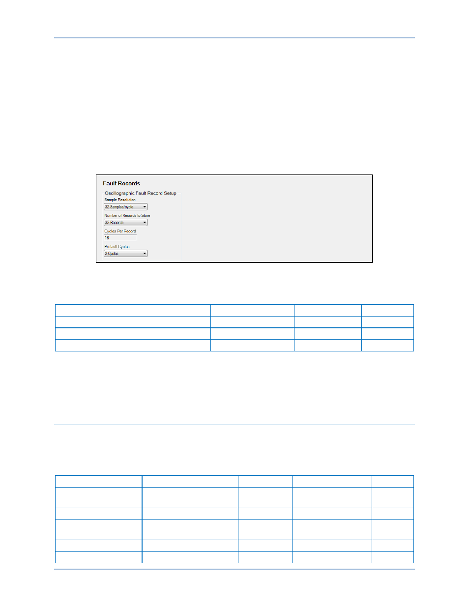
to open the Metering Configuration, Fault Records screen as shown in Figure 140. Enter the values for
Sample Resolution, Number of Records to Store, and Prefault Cycles.
Figure 140. Fault Records Screen
Table 76 summarizes the oscillographic records settings.
Table 76. Oscillographic Records Settings
Setting
Range
Increment
Default
Sample Resolution
32, 16, or 8
n/a
32
Number of Records to Store
32, 16, 8, or 4
n/a
32
Prefault Cycles
0 to 16
1
2
Retrieving Oscillographic Records
Oscillographic records can be downloaded through the Reports, Fault Reports screen in BESTCOMSPlus
(Figure 139). See Fault Reports earlier in this chapter. Oscillographic records can also be downloaded
through the web page interface. For more information, refer to the
chapter.
Distance to Fault
The BE1-11g calculates distance to fault each time a fault record is triggered. Distance to fault is
calculated and displayed based on the power line parameters entered using BESTCOMSPlus or the front-
panel interface. Table 77 provides the power line operating settings.
Table 77. Power Line Operating Settings
Setting
Range
Increment
Unit of Measure
Default
Z1 Line Magnitude
0.05 to 200 (5A CTs)
0.01 to 40 (1A CTs)
varies
ohms
24
Z1 Line Angle
0 to 90
1
degrees
80
Z0 Line Magnitude
0.05 to 650 (5A CTs)
0.01 to 130 (1A CTs)
varies
ohms
8
Z0 Line Angle
0 to 90
1
degrees
80
Line Length
0.01 to 130
0.01
units
100
Fault Reporting
BE1-11g