Element blocking, Logic connections, Operational settings – Basler Electric BE1-11g User Manual
Page 160
148
9424200994 Rev N
Element Blocking
The Block input provides logic-supervision control of the element. When true, the Block input disables the
element by forcing the Trip and Pickup outputs to logic 0 and resetting the element timer. Connect the
element Block input to the desired logic in BESTlogicPlus. When the element is initially selected from the
Elements view, the default condition of the Block input is a logic 0.
Logic Connections
Remote analog input element logic connections are made on the BESTlogicPlus screen in
BESTCOMSPlus. The remote analog input element logic block is illustrated in Figure 93. Logic inputs and
outputs are summarized in Table 56.
Figure 93. Remote Analog Input Element Logic Block
Table 56. Logic Inputs and Outputs
Name
Function
Purpose
Block
Input
Disables the analog input element when true
Trip
Output
True when the analog input element is in trip condition
Pickup
Output
True when the analog input element is in pickup condition
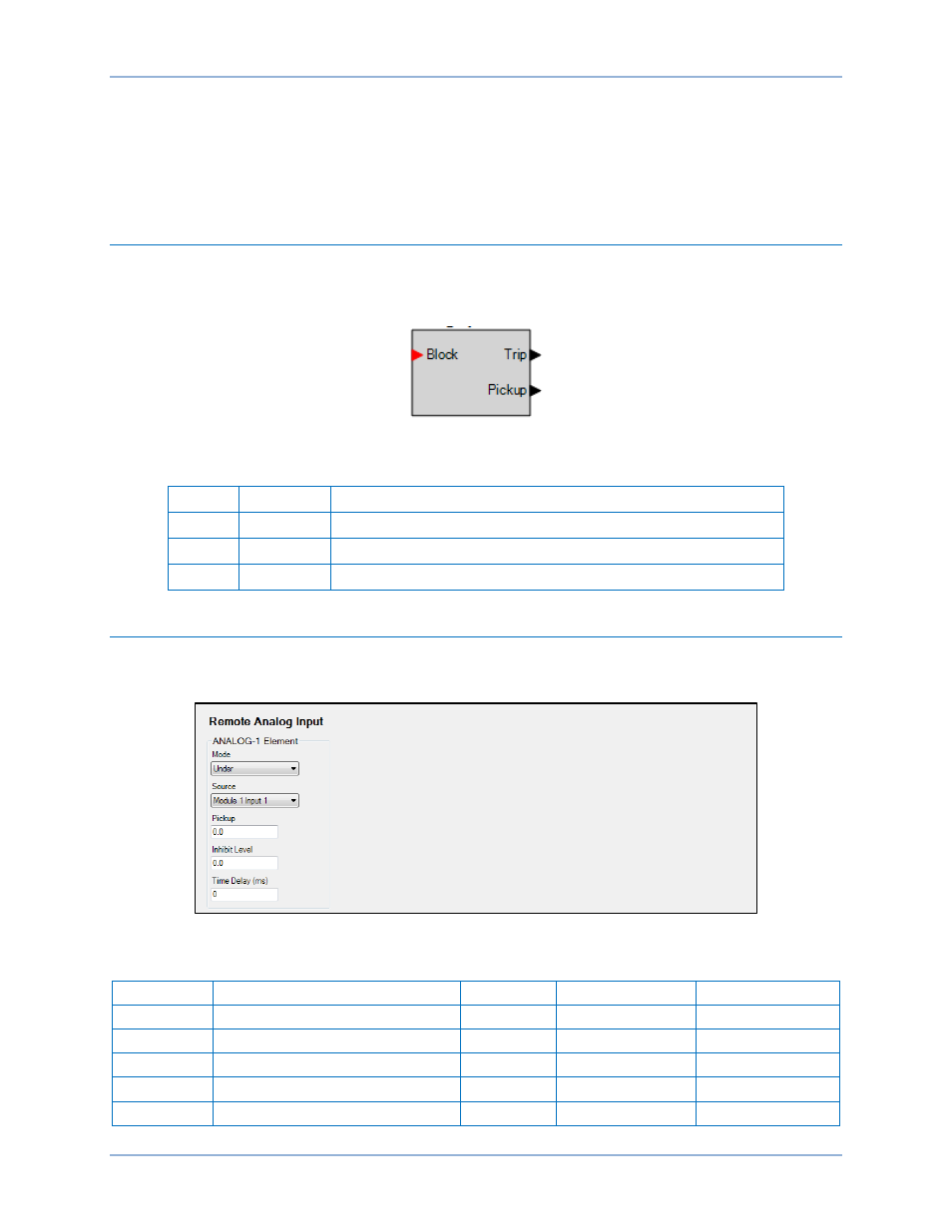
Operational Settings
Remote analog input element operational settings are configured on the Remote Analog Input settings
screen (Figure 94) in BESTCOMSPlus. Setting ranges and defaults are summarized in Table 57.
Figure 94. Remote Analog Input Settings Screen
Table 57. Operational Settings
Setting
Range
Increment
Unit of Measure
Default
Mode
Disabled, Over, or Under
n/a
n/a
Disabled
Source
Module 1 or 2, Input 1, 2, 3, or 4
n/a
n/a
Module 1, Input 1
Pickup
–99,999.9 to 99,999.9
0.1
n/a
0
Inhibit
–99,999.9 to 99,999.9
0.1
n/a
0
Time Delay
0 to 60,000
varies
milliseconds
0
Analog Input Protection
BE1-11g