Dynamic alignment, Altera solutions – Altera POS-PHY Level 4 IP Core User Manual
Page 126
F–2
Appendix F: Static and Dynamic Phase Alignment
Dynamic Alignment
POS-PHY Level 4 IP Core User Guide
December 2014
Altera Corporation
Dynamic Alignment
Dynamic alignment allows for greater skew between the inputs. At the receiver, the
frequency (hence sampling rate) is known, but the actual phase of the data is not. Each
receiver channel looks onto the incoming data and samples at the center of the data
eye. Additional logic is required to account for the skews in sampling the data. These
skews arise when the data is realigned in time to reconstitute the data as it was
originally sent.
The timing margin for a dynamically-aligned system generally excludes the
differential skews between data signals. In this case, the timing margin is calculated
from the clock frequency by subtracting the receiver sampling window, jitter
components, and any sampling errors introduced into the receiver. Transmitter output
delays or skews, or interconnection skews can be ignored because the receiver’s
dynamic phase aligner compensates for them.
Dynamic alignment is appropriate where the skews between signals cannot be
controlled, which is common where signals pass through multiple connectors, or
where devices can be interchanged. It typically provides a much larger timing margin
than static alignment.
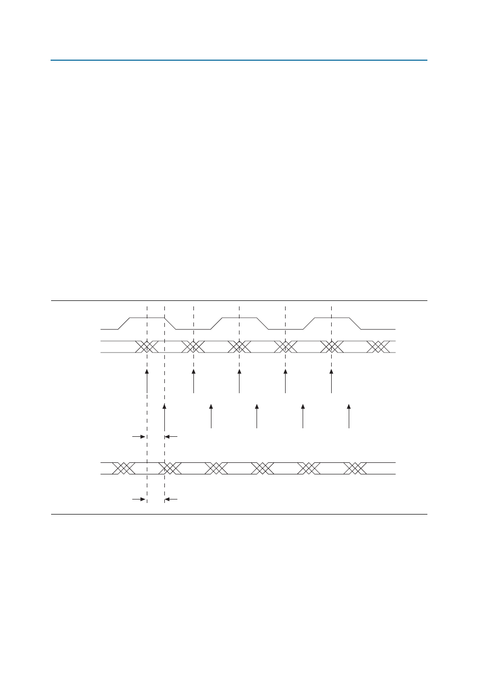
Figure F–2
shows an example of dynamic alignment.
Altera Solutions
Altera supports both static and dynamic alignment as a system solution.
Figure F–2. Dynamic Alignment Timing Diagram
Clock
Data 1
Data 2
Inferred
Sample Clock
Phase Aligned
Sample for
Data 1
Phase Delay
Phase Aligned
Sample for
Data 2
Phase Delay