3 description of the dip switches s3, Dip switch s3/1, Dip switch s3/2 – Metalfab SEW Eurodrive MOVIMOT MM..C User Manual
Page 92: Dip switch s3/3, Dip switch s3/4, Description of the dip switches s3
92
Operating Instructions – MOVIMOT® MM03C - MM3XC
8
Description of the DIP switches S3
Startup with Integrated AS-Interface
8.3
Description of the DIP switches S3
DIP switch S3/1
Motor protection activated or deactivated
•
If the MOVIMOT
®
inverter is mounted close to the motor (with option P2.A or in the
field distributor), the motor protection must be deactivated.
•
To ensure motor protection after all, a TH (bimetallic thermostat) must be used.
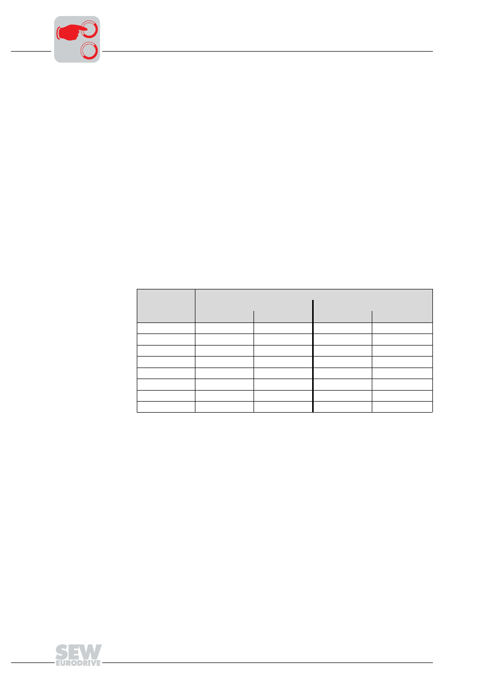
DIP switch S3/2
Motor rating class smaller
•
If it is activated, the DIP switch enables the assignment of MOVIMOT
®
to a motor
with a smaller rating class. The rated power of the unit remains unchanged.
•
If a motor with less power is used, the overload capacity of the drive may increase
since the motor considers the MOVIMOT
®
to be one power increment too high. A
larger current may be impressed for a short period of time, which results in higher
torques.
•
The purpose of switch S3/2 is the short-term utilization of the motor peak torque. The
current limit of the respective unit is always the same, independent of the switch set-
ting. The motor protection function is adapted in reference to the switch setting.
•
In this operating mode with S3/2 = "ON", a pull-out protection of the motor is
not possible.
DIP switch S3/3
Setting the maximum PWM frequency
•
With setting DIP SWITCH S3/3 = OFF, MOVIMOT
®
operates with 4 kHz PWM fre-
quency.
•
With setting DIP SWITCH S3/3 = ON, MOVIMOT
®
operates with a 16 kHz PWM fre-
quency (low noise) and switches back in steps to lower switching frequencies de-
pending on the heat sink temperature.
DIP switch S3/4
No-load damping function (S3/4 = ON)
Upon activation, the function prevents resonant oscillations in no-load operation.
MOVIMOT
®
inverter
Assigned motor
S3/2 = OFF
S3/2 = ON
ᛴ
Ħ
ᛴ
Ħ
MM03
DT71D4
–
MM05
DT80K4
DT71D4
DT71D4
DFR63L4
1)
1) Only possible with offset assembly
MM07
DT80N4
DT80K4
DT80K4
DT71D4
MM11
DT90S4
DT80N4
DT80N4
DT80K4
MM15
DT90L4
DT90S4
DT90S4
DT80N4
MM22
DV100M4
DT90L4
DT90L4
DT90S4
MM30
DV100L4
DV100M4
DV100M4
DT90L4
MM3X
–
DV100L4
DV100L4
DV100M4
0
0
I