Changing the braking torque – Metalfab SEW Eurodrive MOVIMOT MM..C User Manual
Page 147
Operating Instructions – MOVIMOT® MM03C - MM3XC
147
11
Inspection and maintenance work on the brake
Inspection and Maintenance
Changing the
braking torque
The braking torque can be adjusted in steps (see page 148).
•
by installing different brake springs,
•
by changing the number of brake springs.
1. Isolate MOVIMOT
®
from the supply, safeguarding it against unintentional power-up.
2. Remove the following:
– NV16 / NV26 proximity sensor, flange cover or fan guard (21), snap ring (20) and
fan (19), if available.
3. Remove the rubber sealing collar (5).
Remove the manual brake release: Setting nuts (18), conical coil springs (17), studs
(16), releasing lever (15).
4. Loosen the hex nuts (10e) and pull off the brake coil body (12) by approximately 50
mm (caution: brake cable!).
5. Change or add brake springs (11). (Position the brake springs symmetrically.)
6. Re-install brake components except for rubber sealing collar, fan and fan guard. Set
working air gap (see page 145, Points 5 to 7).
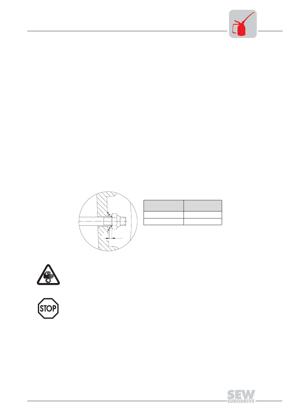
7. With manual brake release:
Set the floating clearance between the conical coil springs (pressed flat) and release
lever via the setting nuts (see the following figure).
8. Install the rubber sealing collar back in place and re-install the removed parts.
01111AXX
Brake
Floating clear-
ance s [mm]
BMG 05 - 1
1.5
BMG 2 - BMG 4
2
s
Important: This floating clearance is necessary so that the pressure plate can
move up as the brake lining wears.
Note: Install new setting nuts (18) and hex nuts (10e) if the removal procedure is
repeated! (due to reduced self-locking of nuts!).