Motor protection, Dip switch – Metalfab SEW Eurodrive MOVIMOT MM..C User Manual
Page 115
Operating Instructions – MOVIMOT® MM03C - MM3XC
115
8
Additional information for mounting close to the motor
Startup with Integrated AS-Interface
8.8
Additional information for mounting close to the motor
Observe the following instructions when mounting the MOVIMOT
®
inverter with option
P2.A close to the motor:
Checking the
method of con-
nection for the
connected motor
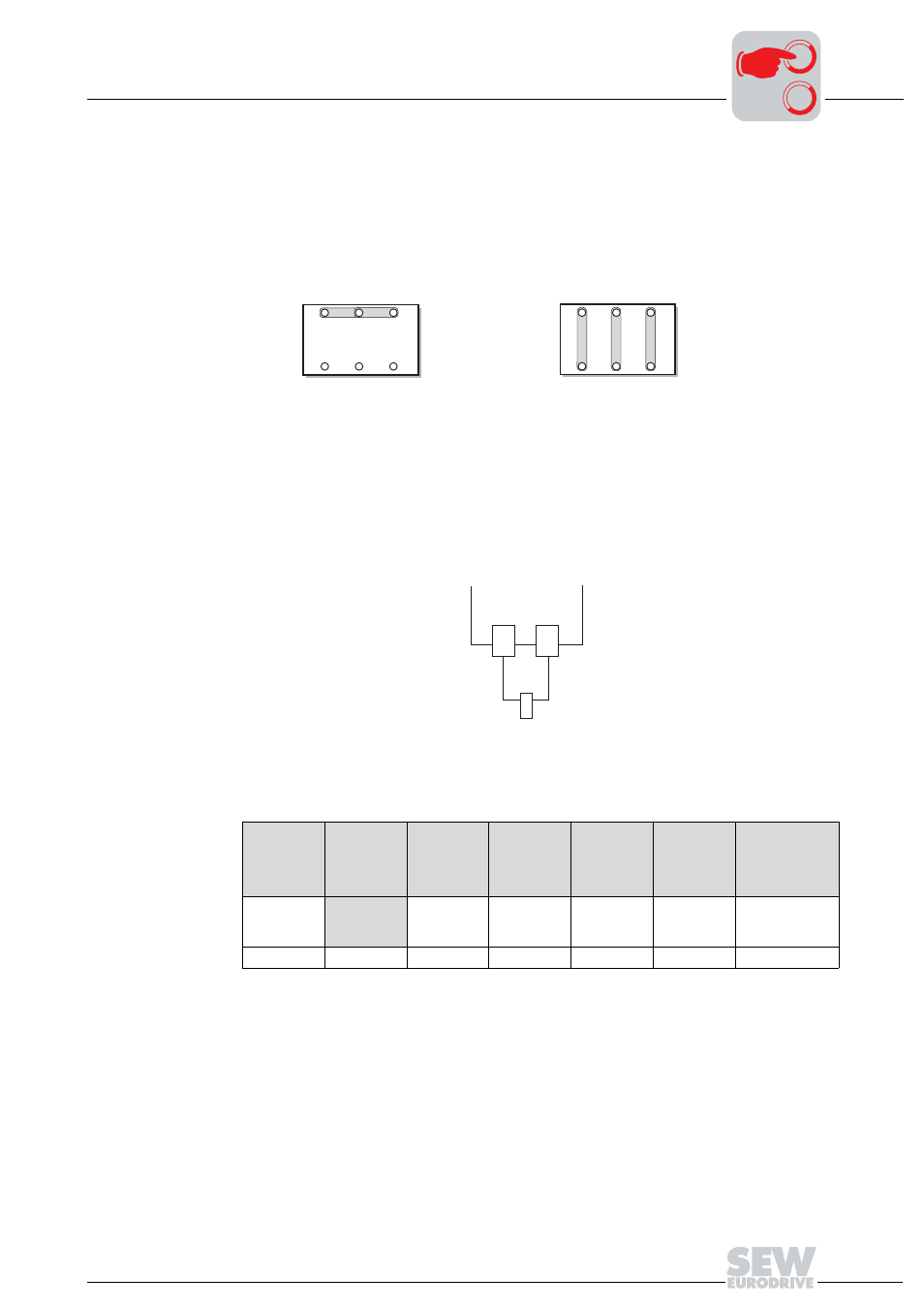
Use the following figure to verify that the selected connection method of MOVIMOT
®
is
identical for the connected motor.
Important: For brake motors: Do not install brake rectifiers inside the terminal box
of the motor!
Motor protection
The connected motor must be equipped with a TH. SEW recommends wiring the TH via
input DI2 (see the following figure).
•
Input DI2 must be monitored be an external control.
•
As soon as DI2 = LOW, the drive must be switched off (bit D0 and D1 = "0").
DIP switch
With mounting of the MOVIMOT
®
inverter close to the motor, set DIP switch S3/1 to ON
which is different than the factory setting.
03636AXX
U1
V1
W1
W2 U2 V2
U1
V1
W1
W2 U2 V2
ᛴ
Ħ
52254AXX
24V
DI2
TH
MOVIMOT
®
S3
1
2
3
4
5
6
Message
Motor
protection
Motor
rating class
PWM
frequency
No-load
damping
Motor type
Brake release
without
Enable
ON
Off
Motor one
size smaller
Variable
(16, 8, 4
kHz)
On
SEW DZ
motor:
1)
1) only available in Brazil
On
OFF
On
adapted
4 kHz
Off
IEC motor
Off
0
0
I