Connection of mbg11a option, Connection of mlk11a option – Metalfab SEW Eurodrive MOVIMOT MM..C User Manual
Page 28
28
Operating Instructions – MOVIMOT® MM03C - MM3XC
5
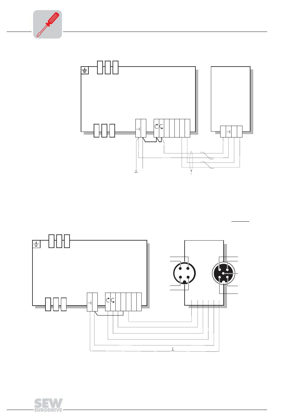
Connection MOVIMOT® options
Electrical Installation of MOVIMOT® Standard Design
Connection of
MBG11A option
The following figure shows the connection of the MBG11A option.
Connection of
MLK11A option
The following illustration shows the connection of the MLK11A option (external AS-i bi-
nary slave).
03183CXX
[1] Observe the enabled direction of rotation (see the section "Connection of MOVIMOT
®
basic unit, Functions of CW/Stop, CCW/Stop terminals with control via RS-485 interface.")
[2] EMC metal cable gland
MBG11A
24V
RS+
RS-
ᛷ
13
14
15
L1
L2
L3
24V
R
L
f1/f2
K1a
K1b
RS-
RS+
MOVIMOT
®
24 V
DC
[2]
[1]
05118CXX
[1] AS-i connection
[2] Connection for two external sensors
4
2
1
3
13
14
15
L1
L2
L3
24V
R
L
f1/f2
K1a
K1b
RS-
RS+
MLK11A
2
1
3
4
5
[2]
AS-i +
AS-i -
24V
DI2
0V
N.C.
N.C.
N.C.
DI3
MOVIMOT
®
[1]
WH
BK/BU
BK/RD
BK/WH
RD
BU
(DI0)
(DO2)
(DO1)
(DO0)
(DO3)
(
)