12 technical data of standard design, 1 iec design with connection voltages 380 vac, 1 iec design with connection voltages 380 v – Metalfab SEW Eurodrive MOVIMOT MM..C User Manual
Page 149
Operating Instructions – MOVIMOT® MM03C - MM3XC
149
12
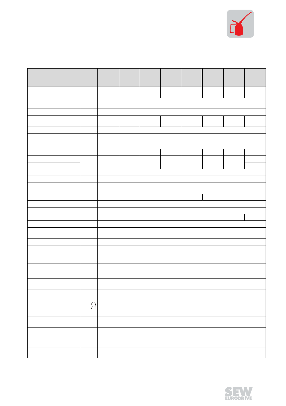
IEC design with connection voltages 380...500 VAC
Technical Data of Standard Design
12
Technical Data of Standard Design
12.1
IEC design with connection voltages 380...500 V
AC
MOVIMOT
®
type
MM 03C-
503-00
MM 05C-
503-00
MM 07C-
503-00
MM 11C-
503-00
MM 15C-
503-00
MM 22C-
503-00
MM 30C-
503-00
MM 3XC-
503-00
Part number
824 115 5
824 116 3
824 117 1
824 118 X
824 119 8
824 120 1
824 121 X
824 180 5
Apparent output power at
V
mains
= 380...500 V
AC
P
rated
1.1 kVA
1.4 kVA
1.8 kVA
2.2 kVA
2.8 kVA
3.8 kVA
5.1 kVA
6.7 kVA
Connection voltages
Permitted range
V
mains
3 x 380 V
AC
/ 400 V
AC
/ 415 V
AC
/ 460 V
AC
/ 500 V
AC
V
in
= 380 V
AC
-10 % ... 500 V
AC
+10 %
Supply frequency
f
mains
50 Hz ... 60 Hz
±
10 %
Rated system current
(at V
mains
= 400 V
AC
)
I
mains
1.3 A
AC
1.6
A
AC
1.9
A
AC
2.4
A
AC
3.5
A
AC
5.0 A
AC
6.7 A
AC
8.6 A
AC
Output voltage
V
out
0...V
in
Output frequency
Resolution
Operating point
f
out
2...100 Hz
0.01 Hz
400 V at 50 Hz / 100 Hz
Rated output current
I
rated
1.6 A
AC
2.0
A
AC
2.5
A
AC
3.2
A
AC
4.0
A
AC
5.5 A
AC
7.3 A
AC
9.6 A
AC
Motor power S1
P
mot
0.37 kW
0.55 kW
0.75 kW
1.1 kW
1.5 kW
2.2 kW
3.0 kW
3.0 kW
Motor power S3 25 % cdf
4.0 kW
PWM frequency
4 (factory setting) / 8 / 16
1)
kHz
1) 16 kHz PWM frequency (low-noise): When DIP SWITCH S1/7 = ON, the units operate with a 16 kHz PWM frequency (low noise) and switch
back in steps to lower switching frequencies depending on the heat sink temperature.
Current limitation
I
max
Motor: 160 % at
ᛴ
and
Ħ
regenerative: 160 % at
ᛴ
and
Ħ
Maximum motor lead
length
15 m when mounting the MOVIMOT
®
frequency inverter close to the motor
(with SEW hybrid cable and option P2.A)
External braking resistor
R
min
150
Ω
68
Ω
Interference immunity
Meets EN 61800–3
Interference emission
Meets EN 61800–3 and class A limit to EN 55011 and EN 55014
Ambient temperature
ϑ
amb
-25 °C...40 °C (P
rated
reduction: 3 % I
N
per K to max. 60 °C)
2)
2) -25 °C...40 °C with S3 25% ED (up to 60 °C with S3 10 % ED)
Climate class
3 K3
Enclosure
(motor-dependent)
IP54, IP55, IP65, IP66 (options, specify when ordering)
IP67 (only available for inverters with terminal box)
Operating mode
DB (EN 60149-1-1 and 1-3), S3 max. cycle duration 10 minutes
Cooling type (DIN 41 751)
Self-cooling
Altitude
h
≤
1000 m (P
rated
reduction: 1 % per 100 m starting at an altitude of 1000 m, see also the section
"Electrical Installation – Installation Instructions")
Ext. power supply to elec-
tronics
Tl. 24 V
V = +24 V
±
25 %, EN 61131-2, residual ripple max. 13 %
I
in
≤
250 mA (typ. 150 mA at 24 V)
Input capacitance 100
µ
F
3 binary inputs
Isolated by opto-coupler, PLC-compatible (EN 61131-2)
R
i
≈
3.0 k
Ω
, I
in
≈
10 mA, sampling time
≤
5 ms
Signal level
+13 V...+30 V = "1" = Contact closed
-3 V...+5 V = "0" = Contact open
Control Functions
Tl. R
Tl. L
Tl. f1/f2
CW/Stop
CCW/Stop
"0" = Setpoint 1 / "1" = Setpoint 2
Output relay
Contact data
Tl. K1a
Tl. K1b
Response time
≤
15 ms
24 V
DC
/ 0.6 A
DC
/ DC11 to IEC 337-1
Signaling function
Normally open contact for ready
signal
Contact made:
– with applied voltage (24 V + supply)
– if no fault was detected
– after self-test phase concluded (after switch-on)
Serial interface
Tl. RS+
Tl. RS-
RS-485