Connection of mwa21a option – Metalfab SEW Eurodrive MOVIMOT MM..C User Manual
Page 29
Operating Instructions – MOVIMOT® MM03C - MM3XC
29
5
Connection MOVIMOT® options
Electrical Installation of MOVIMOT® Standard Design
Connection of
MWA21A option
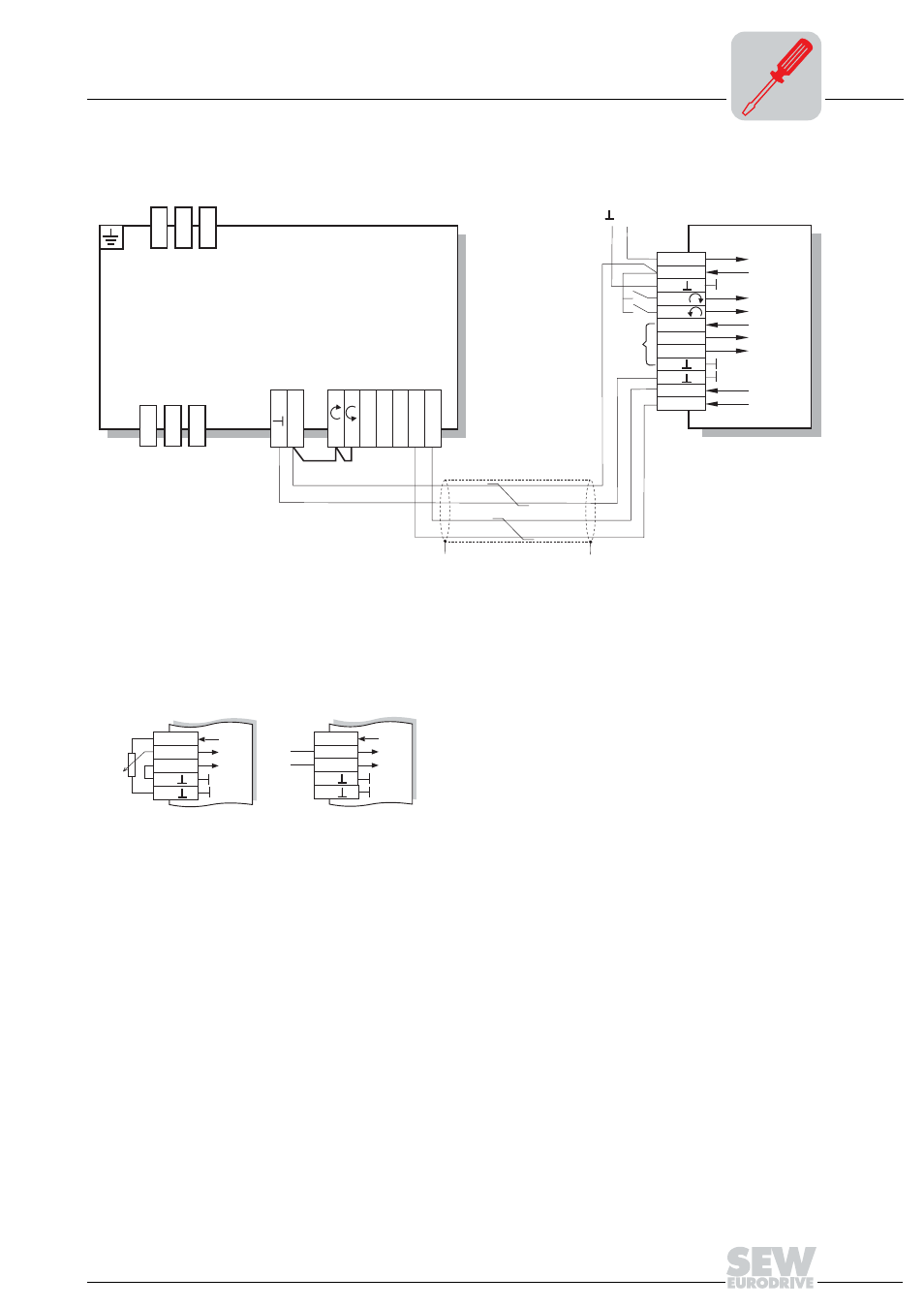
The following figure shows the connection of the MWA21A option.
03184DXX
[1] Note the released direction of rotation
(see the section "Connection of MOVIMOT
®
Basic Unit" Functions of CW/Stop,
CCW/Stop terminals with control via RS-485 interface)
[2] EMC metal cable gland
[3] Potentiometer with integration of 10 V reference voltage [A]
or potential-free analog signal [B]
05622BXX
MWA21A
1 24V
2 24V
3
4 R
5 L
6 10V
7 +
8
-
9
10
11 RS+
12 RS-
24V
DC
13
14
15
L1
L2
L3
24V
R
L
f1/f2
K1a
K1b
RS-
RS+
MOVIMOT
®
ᛷ
ᛷ
[1]
[2]
[2]
[3]
6 10V
7 +
8
-
9
10
6 10V
7 +
8
-
9
10
MW
A21A
MW
A21A
[A]
[B]