4 description of the dip switches s2, Dip switches s2/1, Dip switches s2/2 – Metalfab SEW Eurodrive MOVIMOT MM..C User Manual
Page 55: Description of the dip switches s2
Operating Instructions – MOVIMOT® MM03C - MM3XC
55
7
Description of the DIP switches S2
Startup of Standard Design
7.4
Description of the DIP switches S2
DIP switches
S2/1
Motor type
•
With IEC and NEMA motors, DIP switch S2/1 must always be set to OFF!
•
With DZ motor with rated voltages of 220/380 V, 60 Hz (only available in Brazil), the
DIP switch must always be set to ON.
DIP switches
S2/2
Releasing the brake without enable
With activated switch S2/2 = "ON", the brake can also be released if no drive enable is
present.
Operation with
braking resistor
The special function is not in effect if operated with braking resistor.
Function with ter-
minal control
(address = 0)
With terminal control, the brake can be released by setting terminal f1/f2 if the following
requirements exist:
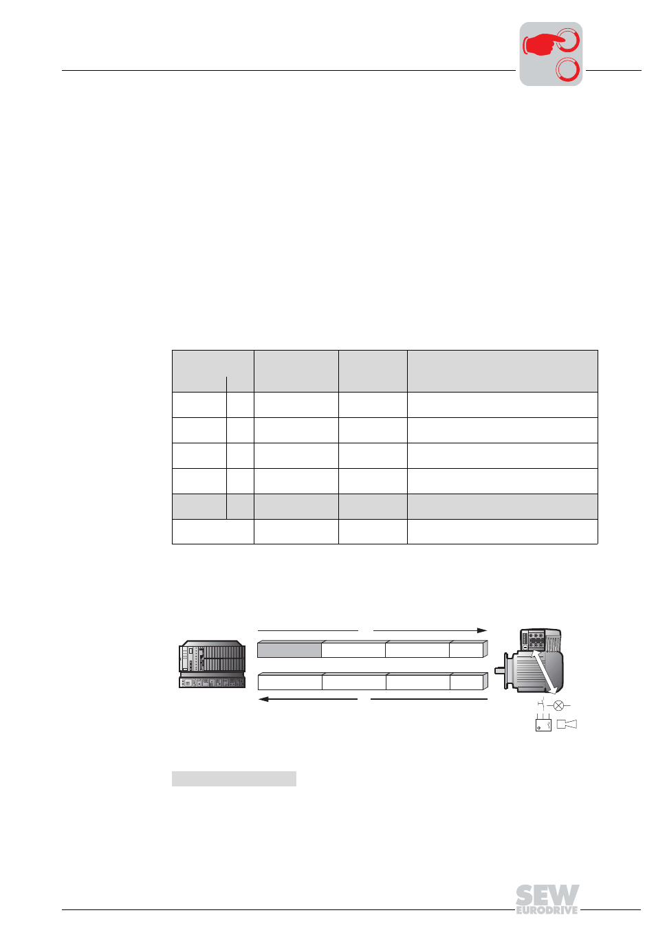
Functions in bus
operation
In bus operation, the brake is released through control in the control word.
Terminal condi-
tion
Enable condition
Fault condi-
tion
Brake function
R
L
f1/f2
"1"
"0"
"0"
"1"
"0"
Unit enabled
No
Unit fault
Brake is controlled by MOVIMOT
®
,
setpoint f1
"1"
"0"
"0"
"1"
"1"
Unit enabled
No
Unit fault
Brake is controlled by MOVIMOT
®
,
setpoint f2
"1"
"0"
"1"
"0"
"0"
Unit not
enabled
No
Unit fault
Brake closed
"1"
"1"
"1"
Unit not
enabled
No
Unit fault
Brake closed
"0"
"0"
"1"
Unit not
enabled
No
Unit fault
Brake released for manual procedure
All conditions pos-
sible
Unit not
enabled
Unit fault
Brake closed
52117AXX
PO = Process output data
PI = Process input data
PO1 = Control word
PI1 = Status word 1
PO2 = Speed (%)
PI2 = Output current
PO3 = Ramp
PI3 = Status word 2
DO = Digital outputs
DI = Digital inputs
MOVIMOT
®
PO1
PO2
PO3
DO
Master
-+
PI1
PI2
PI3
DI
PO
PI
0
0
I