Installing a new brake disk – Metalfab SEW Eurodrive MOVIMOT MM..C User Manual
Page 146
146
Operating Instructions – MOVIMOT® MM03C - MM3XC
11
Inspection and maintenance work on the brake
Inspection and Maintenance
Installing a new
brake disk
When installing a new brake disk, inspect the other removed parts as well and install
new ones if necessary.
1. Isolate MOVIMOT
®
from the supply, safeguarding it against unintentional power-up.
2. Remove the following:
– Proximity sensor NV16 / NV26, if installed
– Flange cover or fan guard (21), circlip (20) and fan (19)
3. Remove the rubber sealing collar (5).
Remove the manual brake release: Setting nuts (18), conical coil springs (17), studs
(16), releasing lever (15).
4. Loosen hexagon nuts (10e), carefully pull off the coil body (12) (Caution, brake ca-
ble!), and take out the brake springs (11).
5. Remove the damping plate (9), pressure plate (8) and brake disk (7, 7b) and clean
the brake components.
6. Install a new brake disk.
7. Re-install brake components (except rubber sealing collar, fan and fan guard). Set
working air gap (page 145, Points 5 to 7).
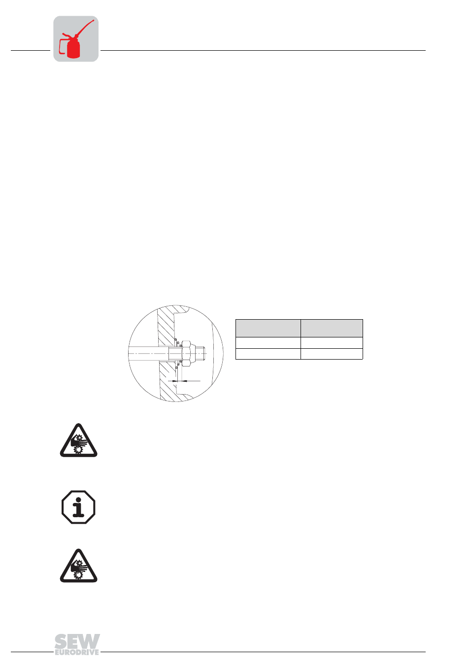
8. With manual brake release (type HF or HR):
Set the floating clearance via the setting nuts between the conical coil springs
(pressed flat) and setting nuts (see the following figure).
9. Install the rubber sealing collar back in place and re-install the removed parts.
06495AXX
Brake
Floating clear-
ance s [mm]
BMG 05 - 1
1,5
BMG 2 - BMG 4
2
s
Important: This floating clearance is necessary so that the pressure plate can
move up as the brake lining wears.
Note:
•
The lockable manual brake release (type HF) is already released if a resistance is
encountered when operating the grub screw.
•
The self-reengaging manual brake release (type HR) can be operated with normal
hand pressure.
Important: In brake motors with self-reengaging manual brake release, the manu-
al brake release lever must be removed after startup/maintenance. A bracket is
provided for storing it on the outside of the motor.