Master reset -122, Master reset, Contacts – Rockwell Automation 1760-xxxx Pico GFX-70 Controllers User Manual User Manual
Page 232
Publication 1760-UM002B-EN-P - March 2005
4-122 Wiring with Pico GFX-70
Master Reset
The master reset function block allows you to reset the state of the markers
and all outputs to the 0 state with a single command. Depending on the
operating mode of this function block, it is possible to reset the outputs only,
or the markers only, or both. 32 function blocks are available.
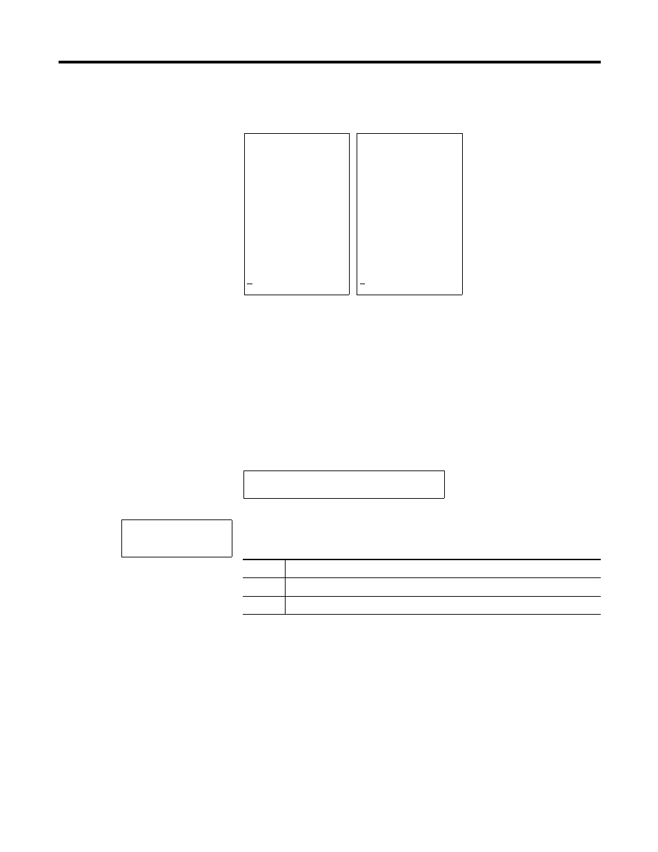
Figure 4.53 Pico GFX-70 circuit diagram with master reset function block
Parameter Display and Parameter Set for the Master Reset Function Block
Operating modes
• Q: Acts on the outputs Q.., *Q.., S.., *S.., *SN.., QA01; *: network
station address
• M: acts on the marker range MD01 to MD48.
• ALL: acts on Q and M.
Contacts
MR01Q1 to MR32Q1
Circuit diagram:
Power flow display: I 01 selected:
Range from jump label 1
processed.
Jump to label 8.
Range to jump label 8 skipped.
Jump label 8, circuit diagram
processed from this point on.
I 01------[ : 01
I 02------[ : 02
: 01
--------
|
-[ Q 01
|
-R Q 02
----------[ : 08
: 02------[ Q 02
Q 02-I 03-T T 02
T 02------[ Q 01
: 08
I 12 -------[ D 01
I 01------[ : 01
I 02--------: 01
: 01
---------
|
[ Q 01
|
R Q 02
----------[ : 08
: 02--------: 08
Q 02--I 03--: 08
T 02--------: 08
: 08
I 12 -------[ D 01
M 96-----------------------------[ MR16T
MR16 Q
+
MR16
Master reset function block number 16
Q
Reset outputs mode
+
Appears in the parameter display