Ladder diagram – Rockwell Automation 1404-M4_M5_M6_M8 Powermonitor 3000 User Manual, PRIOR to Firmware rev. 3.0 User Manual
Page 283
Publication 1404-UM001D-EN-E - October 2004
Sample Applications C-29
Ladder Diagram
IMPORTANT
Words 0 through 3 of the User Configurable Table
Setup array must have specific values.
• Word 0: Powermonitor 3000 password (default =
0)
• Word 1 must be one of the following decimal
values:
– 31, for CSP/PCCC Typed Write
– 1 or 37 for CIP Set Attr Single
• Word 2: zero (0) for writes to table 31 (37). For
configuring instance 1: 0 = all integer table
(instance 1) data type, 1 = all float table (instance
1) data type.
• Word 3: between 1 and 295 incl.
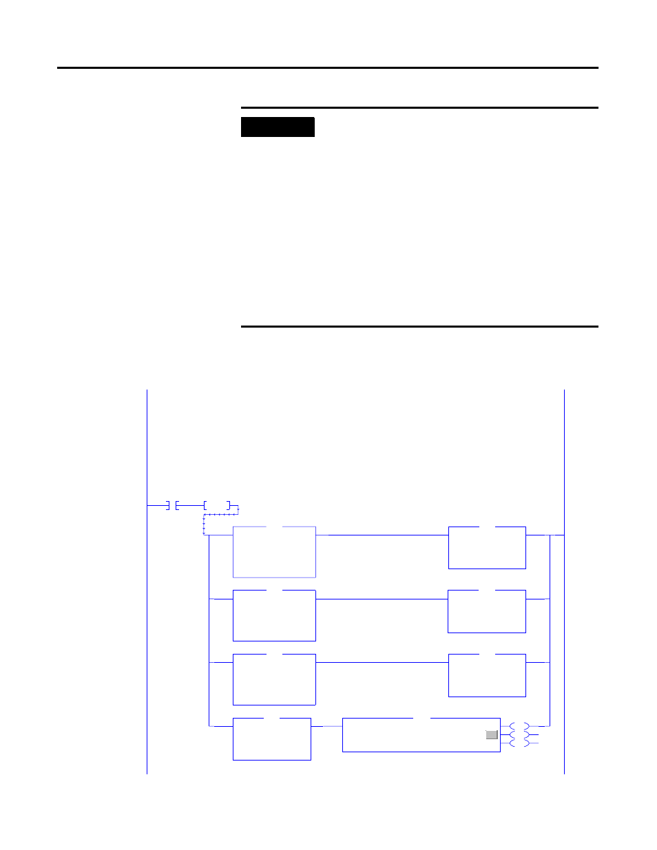
Sample logic program that shows a way to configure a Powermonitor 3000 User Configurable Data Table
from a ControlLogix controller via the 1404-NENET communications option card using Ethernet/IP.
See the accompanying text for a list of tags to be created in the ControlLogix controller.
The first rung allows a selection of tables to write to the PM3000. Enter a 0, 1, or 2 into the tag "Select"
to select between the default table, a custom table, or an "Undo" of the last write. The selected
table is copied into the "Download" table. The rung logic also copies the PM3000 password into the "Download" table .
If the password is changed from the default (0), the new password must be entered into the tag "pwd."
Toggle the "Start" tag to begin.
0
Start
ONS
Oneshot_1
Equal
Source A
Select
2
Source B
0
EQU
Copy File
Source
Default[0]
Dest
Download[0]
Length
26
COP
Equal
Source A
Select
2
Source B
1
EQU
Copy File
Source
Custom[0]
Dest
Download[0]
Length
26
COP
Equal
Source A
Select
2
Source B
2
EQU
Copy File
Source
Old[0]
Dest
Download[0]
Length
26
COP
Copy File
Source
Pwd
Dest
Download[0]
Length
1
COP
EN
DN
ER
Type - PLC-5 Typed Read
Message Control
msgReadOld
...
MSG