Table a.59, H table a.59 – Rockwell Automation 1404-M4_M5_M6_M8 Powermonitor 3000 User Manual, PRIOR to Firmware rev. 3.0 User Manual
Page 243
Publication 1404-UM001D-EN-E - October 2004
Powermonitor 3000 Data Tables A-69
Element
No.
Modbus
Address
Element name
Range
Units
Comment
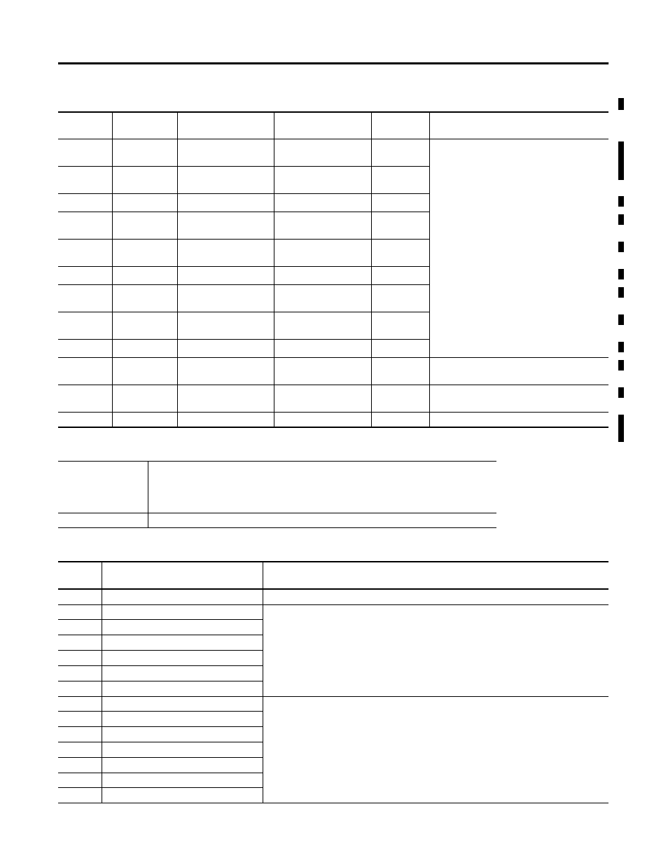
0
32501-02
Off-peak apparent
energy
-999,999.0 to
999,999.0
MVAh
Refer to Reading Time-of-Use Log Data on
page 7-18
1
32503-04
Off-peak apparent
energy
-999.999.999 to
999.999.999
kVAh
2
32505-06
Off-peak demand VA
0.0 to 999.9 x 10
21
VA
3
32507-08
Mid-peak apparent
energy
-999,999.0 to
999,999.0
MVAh
4
32509-10
Mid-peak apparent
energy
-999.999.999 to
999.999.999
kVAh
5
32511-12
Mid-peak demand VA
0.0 to 999.9 x 10
21
VA
6
32513-14
Peak apparent energy
-999,999.0 to
999,999.0
MVAh
7
32515-16
Peak apparent energy
-999.999.999 to
999.999.999
kVAh
8
32517-18
Peak demand VA
0.0 to 999.9 x 10
21
VA
9
32519-20
Start date
000101 to 991231
YYMMDD
Start month / day for data stored in this
record, inclusive
10
32521-22
End date
000101 to 991231
YYMMDD
End month / day for data stored in this
record, inclusive
11
33523-24
Record number
0 to 12
Table A.59 Parameters for Trend Log and Configurable Table
Applies to:
Table A.21 Trend Log Configuration/Read-Back Record Select
Table A.22 Trend Log Results
Table A.30 User-Configured Table Setup
Table A.31 User-Configured Table Results
PM3000 Type
All
Param
No.
Parameter name
Comment
0
None
No parameter
1
Relay output status
Refer to Table A.3 Discrete Data
2
Solid-state KYZ output status
3
Alarm output word
4
Status inputs state
5
Status input #1 counter
6
Status input #2 counter
7
Voltage Mode (Wiring Configuration)
Refer to Table A.4 Basic Device Configuration
8
PT Primary
9
PT Secondary
10
I1/I2/I3 CT Primary
11
I1/I2/I3 CT Secondary
12
I4 CT Primary
13
I4 CT Secondary