Rockwell Automation 294E ArmorStart LT EtherNet/IP Version - User Manual User Manual
Page 52
52
Rockwell Automation Publication 290E-UM001B-EN-P - June 2012
Chapter 2
Installation and Wiring
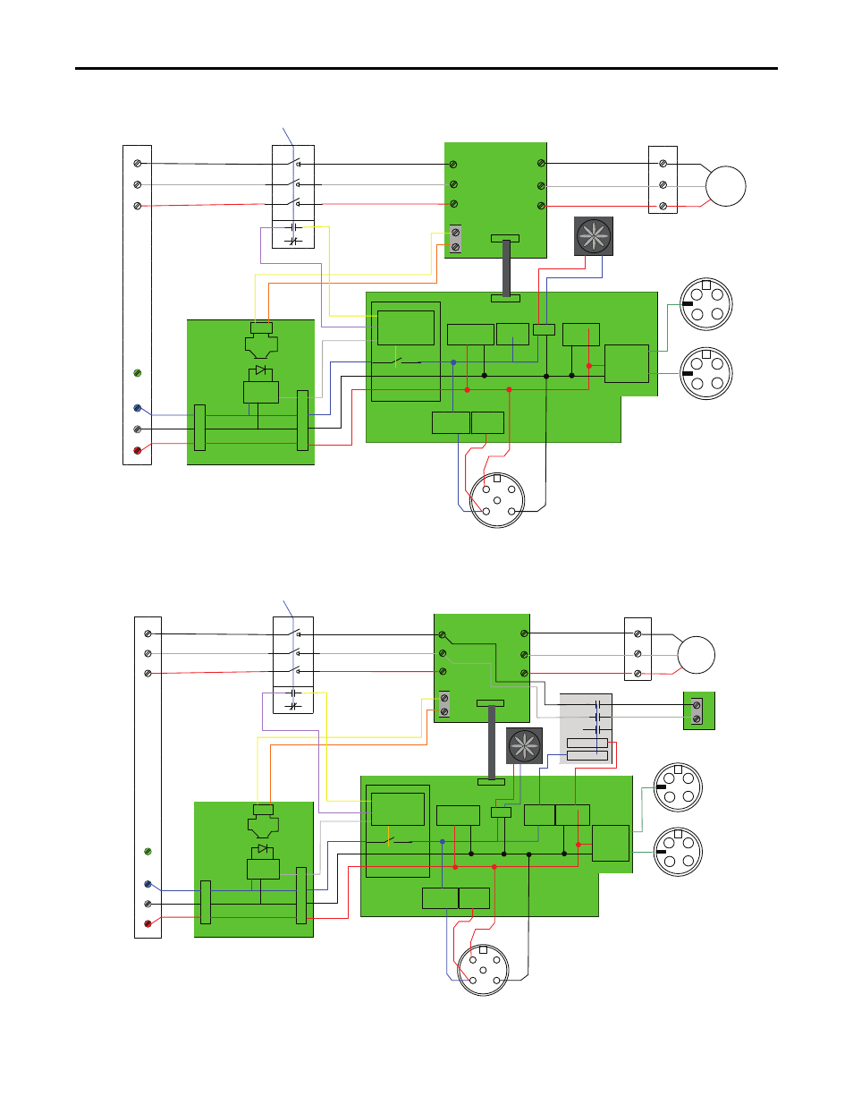
Figure 27 - Bulletin 294E VFD
Figure 28 - Bulletin 294E VFD with -SB
L1
L2
L3
A1
A2
A3
Power
Loss
Switched
(SW)
Un-
Switched
(USW)
Common)
T1
T2
T3
Disconnect
State,
Voltage
Monitoring
and Power Loss
External
Inputs
External
Outputs
Internal
Outputs
Internal
Inputs
Micro
PE
At Motor
Disconnect
Disconnect Status
Power
Conditioning
Board
1
4
2
5
3
Sinking
Input or
Sourcing
output
6-User Configurable I/O pOINTS
EtherNet/IP
Logic
Motor
L1
L2
L3
T1
T2
T3
J3
TB2
1
11
Fan
Drive
Enable
Common
Sensor Voltage
L1
L2
L3
A1
A2
A3
Power
Loss
Switched
(SW)
Un-
Switched
(USW)
Common
T1
T2
T3
Disconnect
State,
Voltage
Monitoring
and Power Loss
External
Inputs
External
Outputs
Internal
Outputs
Internal
Inputs
Micro
PE
At Motor
Disconnect
Disconnect Status
Power
Conditioning
Board
1
4
2
5
3
Sinking
Input or
Sourcing
output
6-User Configurable I/O Points
EtherNet/IP
Logic
Motor
L1
L2
L3
T1
T2
T3
J3
TB2
1
11
Fan
Drive
Enable
Common
Sensor Voltage
Brake
Brake Status
Brake
Control
B1
B2
#16 AWG Minimum
40A BCPD max