Basic operation, Control circuit – Rockwell Automation 294E ArmorStart LT EtherNet/IP Version - User Manual User Manual
Page 27
Rockwell Automation Publication 290E-UM001B-EN-P - June 2012
27
Product Overview
Chapter 1
Basic Operation
Group Motor Installations for USA and Canada Markets
The ArmorStart LT Distributed Motor controllers are listed for use with each
other in group installations per NFPA 79, Electrical Standard for Industrial
Machinery and NFPA 70, the National Electrical Code. When applied according
to the group motor installation requirements, two or more motors are permitted
on a single branch circuit. Group Motor Installation has been successfully used
for many years in the USA and Canada.
Note:
For additional information regarding group motor installations with the
ArmorStart LT Distributed Motor Controller, see
.
Control Circuit
ArmorStart LT accepts a 24V DC Class 2 input power supply for switched
and unswitched power. The control voltage provides power to the inputs
(unswitched) and outputs (switched). Unswitched control voltage is used to
ensure no loss of network connectivity, sensor, or other field input status under
normal operation. The control power terminal connections are labeled A1, A2,
and A3. Switched power is identified as (+A1) (-A2). Unswitched power is
identified as (+A3) (-A2).
As an option, ArmorStart LT can be supplied with an internal power supply
(IPS) eliminating the need for an external control power. The IPS is sourced
from the line side of 3-phase power and is not impacted by the status of the local
at-motor disconnect switch.
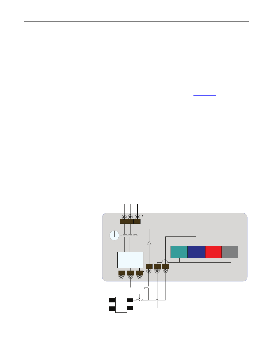
Figure 6 - Control Circuit Wiring Diagram — Single External Power Supply
Outputs
Inputs
EtherNet
Comms
A3
A1
A2
Off
Switched Control Power
Unswitched Control Power
Motor
Control
Motor
Controller
Class 2
External
24VDC Power
Supply
Disconnect
24VDC
+
-
L1
L2
L3
T1
T2
T3
* Control power output is determined by disconnect status
*
ArmorStart LT
L
N