4 cascading (cas), Cascading (cas), Tput – Lenze E94AYAE SM301 User Manual
Page 57: 3safe configuration
Lenze · SM301 safety module · Parameter setting & configuration · DMS 2.3 EN · 11/2013 · TD05
57
3
Safe configuration
3.9
Safety functions
_ _ _ _ _ _ _ _ _ _ _ _ _ _ _ _ _ _ _ _ _ _ _ _ _ _ _ _ _ _ _ _ _ _ _ _ _ _ _ _ _ _ _ _ _ _ _ _ _ _ _ _ _ _ _ _ _ _ _ _ _ _ _ _
3.9.4
Cascading (CAS)
From SM301 V1.1
Tip!
Detailed information on cascade wiring can be found in the manual for the safety module.
Cascading / CAS
Description
This function enables the synchronised shutdown of an entire drive system.
• The function can only be activated via parameter setting. See parameter "CAS: Cascading".
• When the function is active:
• The safe SD-In4 input is used as a cascading input and can no longer be used as universal
input.
• The safe SD-Out1 output is used as a cascading output and can no longer be parameterised
as universal feedback output.
• An emergency stop function (SSE) tripped by cascading cannot be overridden by the
during special operation.
• The cascade triggers with every
, independently of which safety module has the STO
status and for what reason.
• All safety modules of the cascade can only be enabled if all cascading inputs (SD-In4) are in
the OFF state.
Preconditions
• The SD-In4 input must be parameterised as an active input for the "emergency stop" function
and the input delay for SD-In4 must be ≤ 10 ms.
• Via the "SSE: Emergency stop function" parameter,
must be parameterised as the
emergency stop function to be executed.
Emergency stop function (SSE) ( 44)
• The restart behaviour following the execution of the
parameterised to "acknowledged restart".
• The control of the SD-Out1 output via a parameterised safety bus must be inhibited.
• The plausibility check rejects other settings until you have parameterised them correctly.
• In the cascade connection, you can only change from the
/SOS stop function to the
confirmation during special operation. The
stop function would always trigger the
interconnection and a confirmation would thus not be possible.
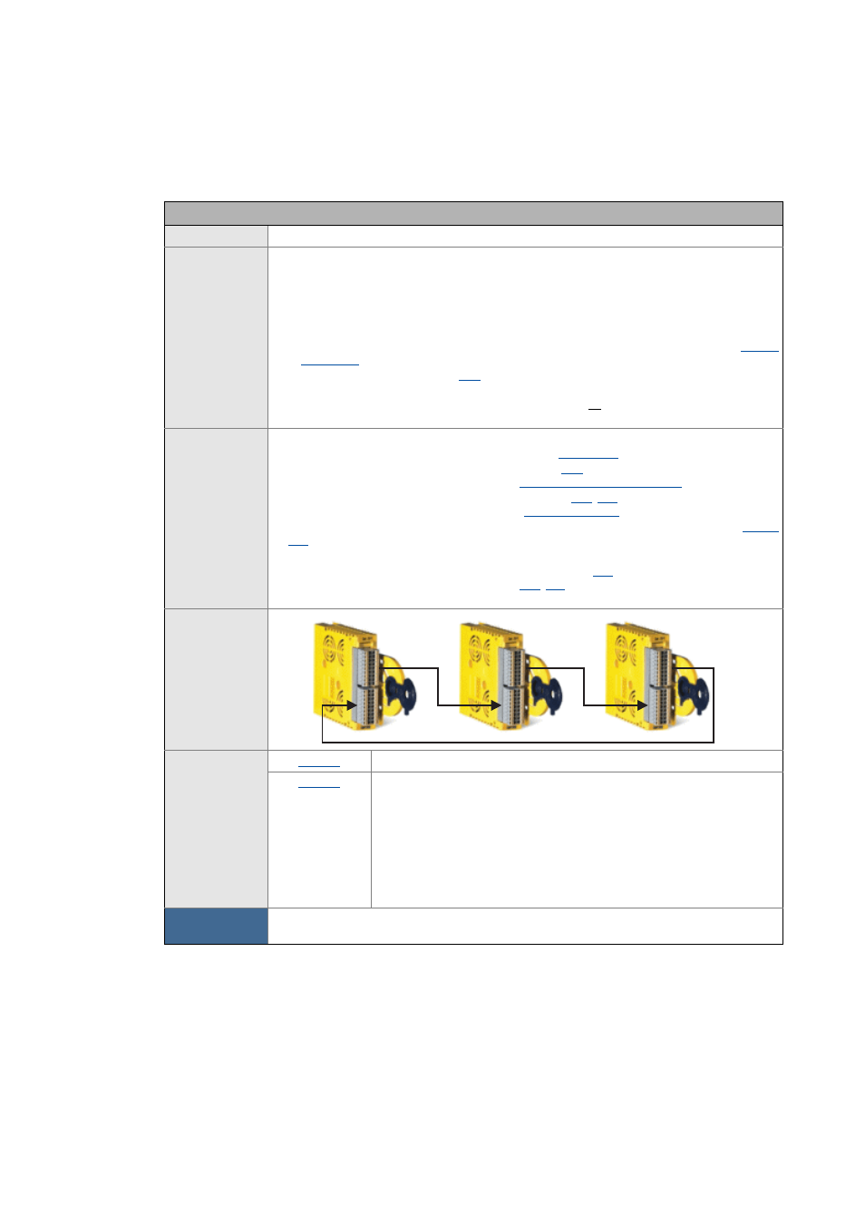
Principle
Parameter
CAS: Cascading
CAS: Stop delay
• Display of the time that passes between switching of the SD-Out1 output
to the OFF state and the detection of the OFF state at the SD-In4 input.
This information can be helpful when commissioning/maintaining the
system.
• If "0 ms" is displayed after a stop, another safety module has triggered
the stop via the cascade.
• The time that passes until the next system acknowledgement is
displayed.
Activate
How to activate the function:
• Set "CAS: Cascading" parameter to "cascading with SD-In4".
SD-Out1
SD-In4
SM301 #1
SM301 #2
SD-In4
SD-Out1
SM301 #n
SD-In4
SD-Out1