2 i/o status information, I/o status information, I/o status information ( 19) – Lenze E94AYAE SM301 User Manual
Page 19: 2introduction, 60[[,2vwdwh
Lenze · SM301 safety module · Parameter setting & configuration · DMS 2.3 EN · 11/2013 · TD05
19
2
Introduction
2.5
Parameter setting & configuration
_ _ _ _ _ _ _ _ _ _ _ _ _ _ _ _ _ _ _ _ _ _ _ _ _ _ _ _ _ _ _ _ _ _ _ _ _ _ _ _ _ _ _ _ _ _ _ _ _ _ _ _ _ _ _ _ _ _ _ _ _ _ _ _
2.5.2.2
I/O status information
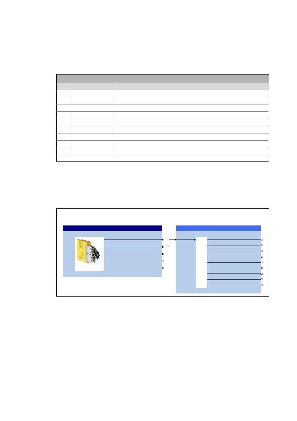
Via the bit-coded status signal SMI_dnloState of the SB LS_SafetyModuleInterface the SM301
safety module transmits the status of the safe inputs and the safe output to the application:
Tip!
For decoding the status signal into individual boolean status signals, simply connect the
output SMI_dnIoState to the L_DevSMStateDecoderIO FB which is available in the function
library from V2.0.
[2-2]
Example: Decoding of the SMI_dnIoState status signal into individual boolean status signals
Bit coding of the SMI_dnIoState status signal
Bit
Name
Meaning
0 SD-In1
Sensor input 1 in ON state.
1 SD-In2
Sensor input 2 in ON state.
2 SD-In3
Sensor input 3 in ON state.
3 SD-In4
Sensor input 4 in ON state.
5 AIS
Restart is acknowledged via terminal (negative edge: 10).
6 AIE
Error is acknowledged via terminal (negative edge: 10).
8 PS_AIS
Restart is acknowledged via safety bus (positive edge: 01).
9 PS_AIE
Error is acknowledged via safety bus (positive edge: 01).
12 SD-Out1
Safe output 1 (feedback output) in the ON state.
Bits not listed are reserved for future extensions!
Note:
This connection example only shows the status signals of the FB L_DevSMStateDecoderIO supported by SM301
V1.1.
60,BGZ&RQWURO
60,BGQ6WDWH
60,BGQ,R6WDWH
60,BE3RZHU6WDJH(QDEOH
60,BE\0RGXOH,G
/6B6DIHW\0RGXOH,QWHUIDFH
6DIHW\PRGXOH
/B'HY606WDWH'HFRGHU,2
GQ,26WDWH
E6DIH'LJ,Q
E6DIH'LJ,Q
E6DIH'LJ,Q
E6DIH'LJ,Q
E$&.,QSXW6WRS
E$&.,QSXW(UURU
E352),VDIH$,6
E352),VDIH$,(
E6DIH'LJ2XW
60[[,2VWDWH