Joystick replacement -13, See 4.2.6 joystick, Replacement – SkyTrak 3606 Service Manual User Manual
Page 99
Cab, Covers and Mirrors
4-13
Steering Wheel Removal
1. Carefully pry the horn cover button out of its recess in
the steering wheel. Disconnect the horn wire lead.
2. Remove the thin M18-1,5 nut securing the steering
wheel to the splined steering column shaft.
3. Use a steering wheel puller to remove the steering
wheel from the splined shaft.
Steering Wheel Installation
1. Install the steering wheel (Fig. 4–12) onto the splined
steering column shaft.
2. Secure the steering wheel with a thin M18-1,5 nut.
Torque the nut to 50 lb/ft (68 Nm).
3. Connect the horn wire lead, then press the horn
cover button into its recess in the steering wheel.
Transmission Shift Control Switch Removal
1. Remove four #10-24 x 5/8" button head screws (item
14, Fig. 4–11) and four #10-24 J-nuts (13) securing
the steering column bottom (5) and top (15) covers
onto the steering column (6).
2. Remove the two #10-32 x 1-1/2" hex socket-head
screws (item 4, Fig. 4–12), #10-32 hex nuts (8) and
#10 lock washers (7) securing the transmission shift
control switch (9) to the steering column (6).
3. Disconnect the electrical connector and remove the
transmission shift control switch (9).
Transmission Shift Control Switch Installation
1. Position the transmission shift control switch (item 9,
Fig. 4–12) onto the steering column (6).
2. Plug the electrical connector in to its harness lead.
3. Attach the transmission shift control switch with two
#10-32 x 1-1/2" hex socket-head screws (4), #10-32
hex nuts (8) and #10 lock washers (7). Tighten the
screws and nuts securely but DO NOT overtighten.
Overtightening will cause the shift control switch to
break.
4. Install the steering column bottom (5) and top (15)
covers onto the steering column. Secure with four
#10-24 x 5/8" button-head screws (14) and #10-24
J-nuts (13). DO NOT overtighten.
Steering Column Removal
1. Remove four #10-24 x 5/8" button-head screws (14)
and #10-24 J-nuts (13) securing the steering column
bottom (5) and top (15) covers onto the steering
column.
2. Disconnect the transmission shift switch (9) and horn
switch leads from the wiring harness.
3. Remove the four 3/8-16 x 1" hex socket-head screws
(12) and 3/8 lock washers (11) securing the steering
column (6) to the steering valve.
4. Remove the steering column from the cab.
Steering Column Installation
1. Position the steering column (item 6, Fig. 4–12)
within the cab and engage the splined lower end of
the steering shaft with the power steering valve.
Press the steering column shaft down into the power
steering valve. Fully engage the splines.
2. Align the four steering column mounting holes with
the dash panel and power steering valve mounting
holes. Secure the steering column with four 3/8-16 x
1" hex socket-head screws (12) and 3/8 lock washers
(11). Torque to 31 lb/ft (42 Nm).
3. Connect the transmission shift switch (9) and horn
switch leads to the wiring harness.
4. Install the steering column bottom (5) and top (15)
covers onto the steering column. Secure with four
#10-24 x 5/8" button-head screws (14) and #10-24
J-nuts (13).
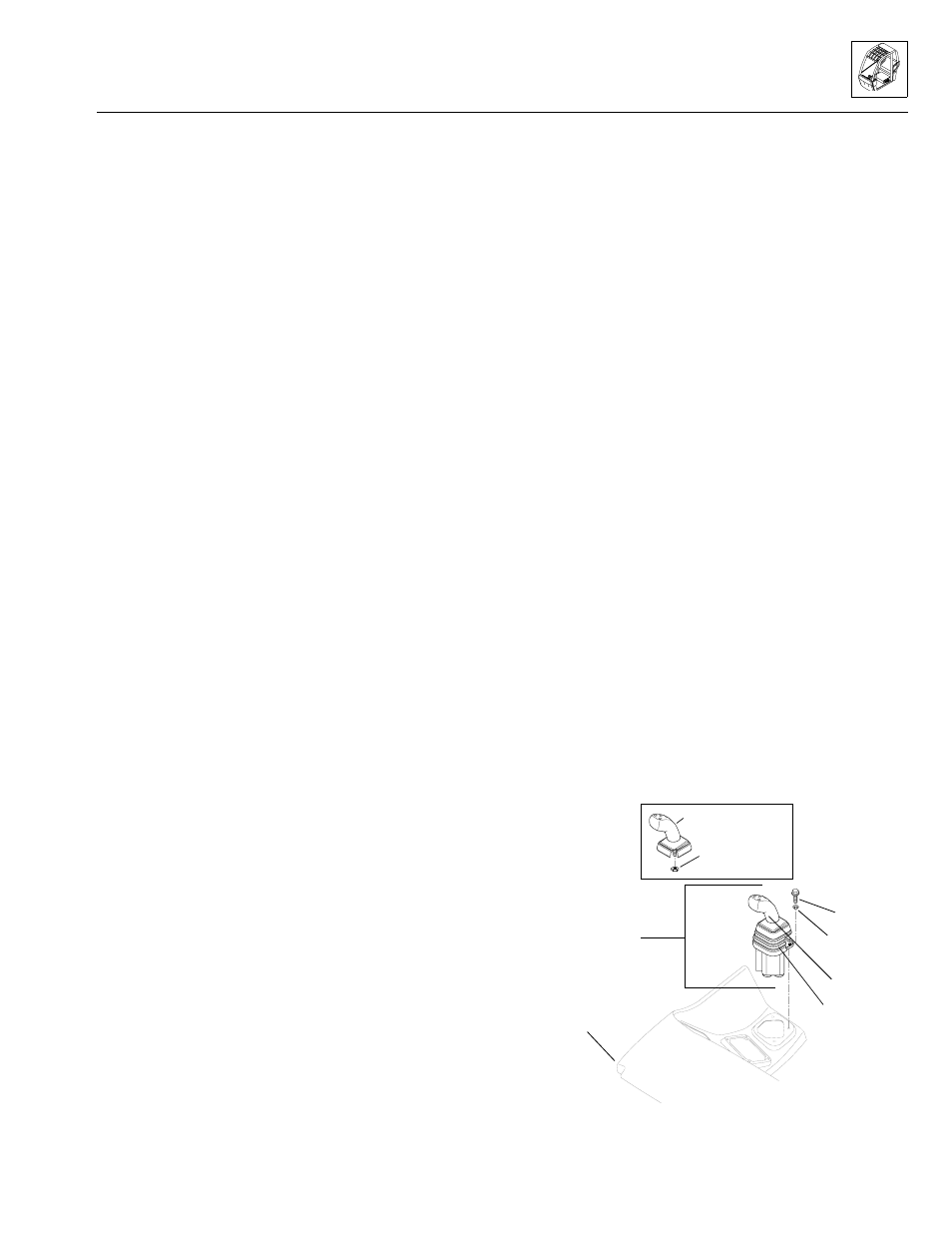
4.2.6 Joystick Replacement
A. Joystick Handle Replacement
Joystick Handle Removal
1. Remove the rubber boot (Fig. 4–13) from the joystick.
Slide the boot up and over the joystick to reveal
wiring, a threaded shaft and mounting nut (jam nut).
2. Disconnect the wiring and loosen the upper jam nut
securing the joystick to its base. Remove the joystick.
Figure 4–13. Joystick mounting arrangement.
MS0920
Joystick handle
(boot removed)
Mounting nut
(jam nut)
Joystick
assembly
Front dash
(ref.)
1/4-20 x 1"
capscrew
1/4"
lockwasher
Joystick
Rubber boot
Model 3606 • Origin 10/99