SkyTrak 3606 Service Manual User Manual
Page 386
Section 10
10-68
Model 3606 • Origin 10/99
a. Joystick Button Testing
1. Remove the four button-head capscrews (Fig. 10– 76)
securing the logic panel to the side console.
Figure 10– 76. Logic panel mounting detail.
2. Carefully pry the panel up away from the console and
locate the six-wire connector that comes from the
joystick (Fig. 10– 77).
Figure 10– 77. Logic panel to joystick wire connector.
3. Inspect the wiring and connector plug for obvious
signs of shorts, damage, etc.
4. Disconnect the harness half. Test only the joystick
half.
5. Using an ohm/volt meter, test for continuity in the
joystick button switches when they are depressed.
The wiring should have zero (0) ohms of resistance
when testing with an ohm/volt meter. Using the chart
below and the wiring schematic in Fig. 10– 75, test
each joystick button switch for proper functioning.
Joystick Wire Color / Function Chart
YELLOW
Common Wire
GREEN
Middle Button
WHITE
Top Left
BLUE
Top Right Button
RED
Front Button
Battery positive (+) is accessed via wire 43, the fused
GRY/BRN 16-gauge wire. The ground wire, 2E, is a black
(BLK) 16-gauge wire.
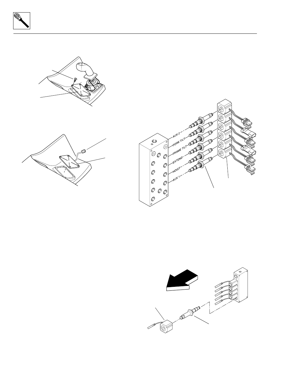
b. Joystick Function Solenoid Valves
Joystick commands are actuated both electrically and
hydraulically via a set of solenoid-operated control valves
mounted in an array at the pilot select manifold
(Fig. 10– 78). The pilot select manifold is located inside
the rear cover on the left side of the frame.
As the solenoid coils are energized/de-energized, the
cartridge valves work to open and close oil passages
(Fig. 10– 79), thereby directing hydraulic fluid flow to the
proper hydraulic circuit for the function selected.
Figure 10– 78. Pilot select manifold.
Solenoid Coil and Cartridge Valve Replacement
If a solenoid coil (Fig. 10– 79) is suspected of malfunc-
tioning, disconnect the coil wiring lead and test the coil.
Also inspect the valve cartridge, O-rings, and the other
hydraulic and electrical components in the circuit to accu-
rately determine the cause of the problem.
Figure 10– 79. Solenoid and cartridge valve detail.
Button-head
Capscrew
Logic Panel
SS1210
MS2540
Logic Panel
Six-wire
Connector
MS2440
Pilot Select
Manifold
Cartridge Valve
Solenoid Coil
MS2480
Pilot Select
Manifold
Cartridge Valve
Solenoid Coil
FRONT