S (fig. 9– 68), Frame tilt and stabilizer cylinder legend – SkyTrak 3606 Service Manual User Manual
Page 295
Hydraulic System
9-101
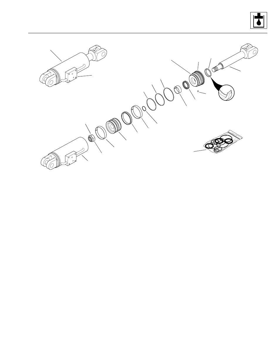
Figure 9– 68. Frame tilt and/or stabilizer cylinder.
Frame Tilt and Stabilizer Cylinder Legend
1. Frame Tilt/Stabilizer Cylinder
2. Tube
3. Lock Nut, 1.50 - 12 UN
4. Precision Wearband
5. Piston
6. Capped T-Seal, Type 730
7. O-Ring
8. O-Ring
9. Backup Ring
10. O-Ring
11. Precision Wearband
12. Deep Z-Seal with Rod Backup
13. Locking Insert
14. Head Gland
15. Heavy-duty Rod Wiper, Sealed OD
16. Weldment Rod
KITS
17. Seal Kit (includes items 4, 6-13, & 15)
b. Frame Tilt or Stabilizer Cylinder Disassembly
Note: An additional O-ring may be included at the base
of the cylinder rod. This additional O-ring may be
discarded, as it served only in a temporarily protective
role to keep paint off the rod while the cylinder was
painted at the factory.
1. Clamp the cylinder (1, Fig. 9– 68) in a soft-jawed vise
or other holding device, and place a suitable
container beneath the cylinder to catch hydraulic fluid
run-off.
2. Remove the manifold block from the mounting boss
(ref.) as required. Loosen the 3/8-16 x 3-3/4" hex-
head capscrews securing the manifold block to the
cylinder mounting boss in an alternating pattern.
Note: Significant pressure may be trapped inside the
cylinder. Exercise caution when removing the manifold
block.
3. Remove the 3/8-16 x 3-3/4" hex-head capscrews, 3/
8" lockwashers, four SAE 3/8" washers, and O-rings.
Remove the dual pilot-operated check manifold from
the cylinder at the manifold block mounting boss
(ref.).
PF0760
PS0570
Apply Loctite #271 and Torque
to 1100-1250 lb/ft.
(1492-1695 Nm)
Torque to 300-400 lb/ft.
(407-542 Nm)
Manifold Block
Mounting Boss (ref.)
Model 3606 • Origin 10/99