SkyTrak 3606 Service Manual User Manual
Page 359
Electrical System
10-41
Model 3606 • Origin 10/99
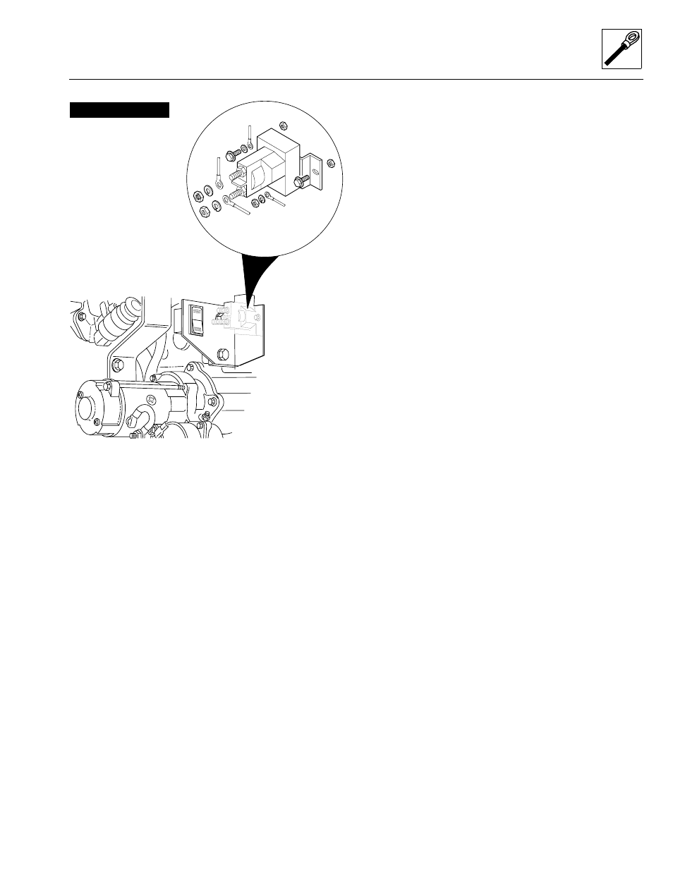
Figure 10– 31. Cummins starter relay.
The relay is internally grounded and is equipped with two
large terminals and one small terminal. The two large ter-
minals are for connection between the battery and the
starter. The small terminal is located on the lower side of
the relay is for connection to the ignition key switch.
Turning the ignition key switch with the transmission in
NEUTRAL (N) allows current to flow through the relay
coil via terminal to the ground point on the casing. The
flow of current energizes the coil, forming a magnetic
field that attracts a movable contact. When the contacts
fully close, current from the battery is allowed to flow to
the starter through the relay.
When the ignition switch is released, the flow of current
to the coil is stopped. The magnetic field is broken, and
the return spring opens the contacts, stopping current
flow from the battery to the starter.
a. Starter Relay Removal
1. Disconnect the negative (-) battery cable at the
battery.
2. Remove the hex nut (9), lockwasher (8) and the
orange/black wire #55 (5) from the relay.
3. Remove hex nut (9), lockwasher (8) and the pink and
brown wire #54 (item 6) from the relay terminal stud.
4. Remove small hex nut (11), small lockwasher (10)
and the yellow and blue wire #4 (item 7) from the
relay terminal stud.
5. Remove the two 1/4-20 x 3/4 hex-head capscrews,
(2) 1/4-20 hex-lock elastic nuts securing the starter
relay to the mount bracket. Remove the flat washer
(3) the black ground wire #2A (4) from one of the
capscrews.
6. Remove the relay from the vehicle.
The starter relay is a non-serviceable part and must be
replaced if defective.
b. Starter Relay Inspection and Testing
Inspect the general condition of the starter relay casing
and terminals. Replace the relay if it is cracked or dam-
aged in any way.
To test the operation of the starter relay, connect a 12-volt
DC positive lead to the positive terminal (the “top” termi-
nal). Connect the negative lead to the mounting bracket,
listening for a “click” sound as the contacts close.
Replace the relay if the contacts do not close.
c. Starter Relay Installation
1. Position the black ground wire #2A (4) on a 1/4-20 x
3/4 hex-head capscrew (2). Insert the capscrew
through the left mount hole on the starter relay (1).
Secure the relay to the relay mount plate with the
other 1/4-20 x 3/4 hex-head capscrew and two 1/4-20
hex-lock elastic nuts. Torque to 9 lb/ft (12 Nm).
2. Install the yellow/blue wire #4 (7) onto the relay
terminal stud. Secure with the small lockwasher (10)
and small hex nut (11).
3. Install the pink/brown wire #54 (6) onto the relay
terminal stud. Secure with lockwasher (8) and hex
nut (9).
4. Install the orange/black wire #55 (5) onto the relay
terminal stud. Secure with lockwasher (8) and hex
nut (9).
5. Connect the negative (-) battery cable at the battery.
1. Starter Relay
2. Mounting Hardware
3. Flat Washer
4. Wire #2A BLK Ground
5. Wire #55 ORG/BLK
Ignition Wire
6. Wire #54 PNK/BRN
to Starter
7. Wire #4 YEL/BLU
Transmission Neutral
Switch to Starter Relay
8. Lockwashers
9. Hex Nuts
10. “Small” Lockwashers
11. “Small” Hex Nuts
CUMMINS ENGINE
MS1630