SkyTrak 3606 Service Manual User Manual
Page 218
Section 9
9-24
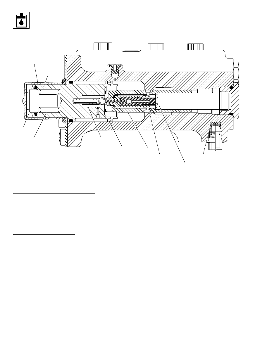
Figure 9– 14. Cross section of service brake valve.
Fluid Flow When Brake Pedal is Pressed
System pressure from the main pump flows to the
unloader valve, to the auxiliary function manifold, to the
brake valve. With the pedal depressed, spool valves open
and oil is allowed to flow through the brake valve and out
to the axles.
Service Brake Valve Operation
Valve operation occurs in two modes, Power Mode and
Manual Mode. The steps below describe service brake
valve function in both of those modes.
Power Mode
1. Displacement of the brake pedal is transmitted to the
valve at the plunger (Fig. 9– 14).
2. The series spring transmits plunger displacement to
the piston. The series spring also absorbs slight
pedal pressure variations, and helps to provide
smoother braking.
3. At rest (or “standby”), system pressure exists at the
service brake valve, and the lines are vented to the
reservoir. The reservoir venting is restricted as pedal
pressure is applied, causing the piston to contact the
piston sealing ring. The piston is blocked when the
fluid return metering notches on the spool are
covered by the spool bore.
4. Pressure in both the front and rear axle brake lines is
equal. A groove in each of the two spools opens to a
cross-hole between the two spool bores, preventing
uneven brake pressure. This feature is called the
equalizer function.
5. Power-mode braking begins when the metering
notches in the spool meter oil from the inlet port to
the spool chamber. Oil flows from the spool chamber,
through the one-way orifice, and into the brake lines.
Brake pressure is controlled by a force balance
between the force applied at the pedal and the
resulting force from pressure in the spool area.
6. The load sense bleed orifice helps provide stability
and aids in purging air from the system.
Manual Mode
In the event that hydraulic pressure at the inlet port is too
low to provide the braking force required, the service
brake valve automatically transitions to the manual mode
to provide braking power.
Flow paths out of the valve that would rob efficiency are
automatically blocked in the manual mode. The inlet port
check valve seals off the inlet port, and the load sense
shutoff valve closes. The service brake valve then acts as
a two-stage pump.
MS1880
Rubber Boot
Piston
Plunger
Series Spring
Relief Valve
Piston Ring
Spool
Metering Notches
One-way Orifice
Make-up Check with
Load Sense Spool
Model 3606 • Origin 10/99