Der (1, fig. 9– 75, 1, fig. 9– 75, Side tilt carriage cylinder legend – SkyTrak 3606 Service Manual User Manual
Page 308
Section 9
9-114
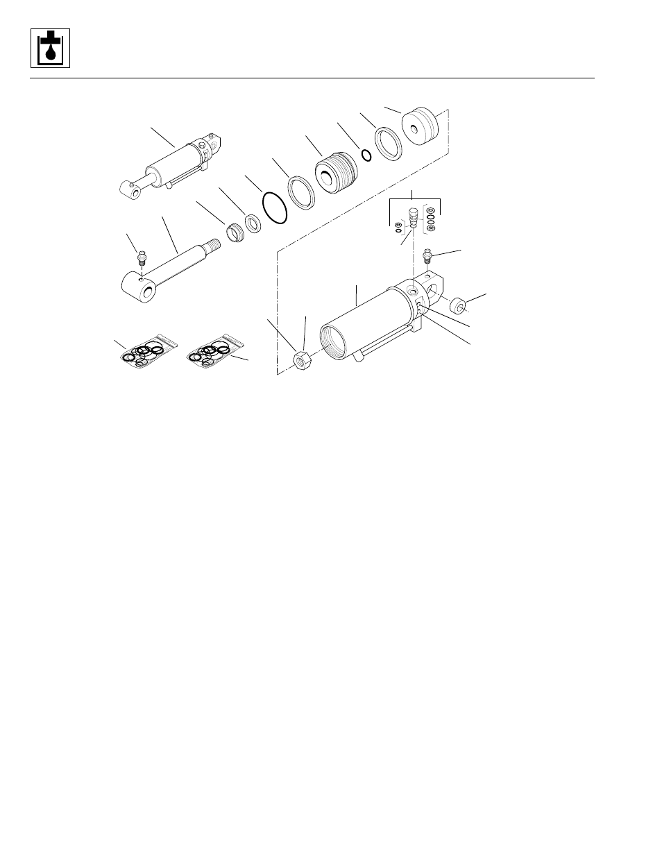
Figure 9– 75. Side tilt carriage cylinder (optional).
Side Tilt Carriage Cylinder Legend
1. Side Tilt Carriage Cylinder (OPTIONAL)
2. Cylinder Tube
3. Pilot Check Valve
4. Piston
5. Gland
6. Rod
7. Piston Nut
8. Self-aligning Bearing
9. Rod Seal
10. Wiper
11. O-Ring
12. Backup Ring
13. O-Ring
14. Piston Seal
15. Grease Fitting
KITS
16. Side Tilt Carriage Cylinder Seal Kit
(includes items 9-14)
17. Pilot Check Valve Seal Kit for item 3
b. Side Tilt Carriage Cylinder Disassembly
Note: An additional O-ring may be included at the base
of the cylinder rod. This additional O-ring may be
discarded, as it served only in a temporarily protective
role to keep paint off the rod while the cylinder was
painted at the factory.
1. Clean the side tilt carriage cylinder (1, Fig. 9– 75) with
a suitable cleaner to remove dirt, debris, grease, etc.
2. If necessary, remove both grease fittings (15) from
the cylinder tube eyelet.
3. If necessary, press the self-align bearing (8) from the
cylinder tube eyelet.
4. Place the side tilt carriage cylinder (1) in a soft-jawed
vise or other acceptable holding equipment if
possible. DO NOT damage the tube (2).
Note: Significant pressure may be trapped inside the
cylinder. Exercise caution when removing the pilot check
valves (3) from the side tilt carriage cylinder.
5. Remove both pilot check valves (3) from the side tilt
carriage cylinder. Remove the O-rings and backup
rings from the pilot check valves.
6. Extend the rod (6) to allow access to the base of the
cylinder.
PH0800
Apply Loctite #271 to
Threads and Torque to
350 lb/ft. (474,6 Nm)
Torque to 30-35 lb/ft.
(40,7-47,5 Nm)
Extend Port
Retract Port
PF0760
Model 3606 • Origin 10/99