Electrical system – SkyTrak 3606 Service Manual User Manual
Page 373
Electrical System
10-55
Model 3606 • Origin 10/99
If the key binds in the switch, check the key for defects
and the switch for foreign objects. Clean or remove for-
eign material from the key as required. Check that the
key is not bent or excessively worn; replace a bent or
worn key with a new key. Apply powdered graphite to the
key and insert and withdraw the key from the switch sev-
eral times to distribute the graphite into the switch lock
mechanism.
During freezing temperatures, if the ignition switch fails to
turn, or does not allow the key to be inserted, warm the
switch with a heat gun (blow dryer), or use liquid lock
deicer to help evaporate frozen moisture from within the
switch.
IMPORTANT: Only use graphite or a liquid lock deicer
within the switch. Replace a defective switch.
Ignition Switch Removal
1. Disconnect the negative (-) battery cable at the
negative battery terminal (Fig. 10– 49).
2. Remove the hex nut securing the ignition switch to
the dash.
3. Reach up and under the dash to work the ignition
switch and wiring out of the mounting hole.
4. Label the wires on the ignition switch. Disconnect the
wires from the switch and remove the switch from the
vehicle.
Disassembly
DO NOT disassemble the ignition switch. Replace a
defective switch with a new one.
Inspection and Replacement
The key should insert and turn freely in the switch. If the
key binds in the switch, check the key for defects and the
switch for foreign objects. Clean or remove foreign mate-
rial from the key as required. Check that the key is not
bent or excessively worn; replace a bent or worn key with
a new key. Apply powdered graphite to the key and insert
and withdraw the key from the switch several times to dis-
tribute the graphite into the switch lock mechanism.
IMPORTANT: Only use graphite or a liquid lock deicer
within the switch. Replace a defective switch.
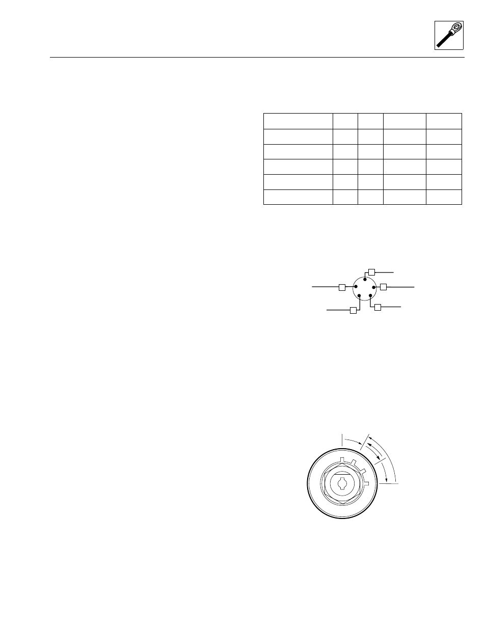
Refer to the SWITCH POSITION table below. Using an
ohmmeter or a continuity tester, check for continuity.
Replace the switch if it fails to test according to the table.
Ignition Switch Installation
1. Connect the wires according to the labels applied
during removal. Follow the ignition key switch wiring
diagram (Fig. 10– 53) as required.
Figure 10– 53. Ignition key switch wiring diagram.
2. Reach up and under the dash to work the ignition
switch and wiring into the ignition switch-mounting
hole on the left side of the dash (Fig. 10– 52).
3. Align the ignition switch so that when it is in the OFF
position (Fig. 10– 54), the key slot is positioned
vertically (straight up and down). Install the hex nut
securing the ignition switch to the dash. DO NOT
overtighten.
Figure 10– 54. Ignition key switch positions.
SWITCH POSITION
Switch Terminals
OFF
RUN
PREHEAT
START
1. BAT
X
X
X
2. IGN
X
X
X
3. START
X
4. ACC
X
5. PREHEAT
X
X
5
6
IGNITION
SWITCH
15
PUR
YEL/RED
5
2
1
4
3
77
DK GRN
BRN
ORN
7
To MAIN Fuse
To Switched Grid
To 15-Amp Fuse
To Positive (+) Grid
To 7.5-Amp Fuse
(fuse panel bus)
(fuse panel bus)
MS2430
OF0390
OFF
RUN
PREHEAT
START