Boom extend/retract circuit -28 – SkyTrak 3606 Service Manual User Manual
Page 222
Section 9
9-28
Model 3606 • Origin 10/99
9.8.3
Boom Extend/Retract Circuit
Hydraulic flow is applied in the boom extend/retract cir-
cuit (Fig. 9– 17 and Fig. 9– 18) by the hydraulic gear
pump. System pressure is directed to either side of the
extend/retract cylinder by the shifting of the spool valve in
the directional control valve of the main control valve. The
spool valve is shifted by pilot pressure, regulated by the
position of the joystick.
a. Center Position
When the joystick is in the center or NEUTRAL (N) posi-
tion, the extend/retract spool valve (Fig. 9– 17) in the main
control valve is centered so system pressure cannot flow
through the ports to the cylinder. No boom movement
occurs with the joystick in the center position.
b. Extend Position
When the joystick is in the boom EXTEND position, the
spool valve (Fig. 9– 17) is shifted by pilot pressure so flow
is directed through extend/retract spool valve ports A-D,
then E-B, through the check valve to the base end of the
extend/retract cylinder. If system pressure exceeds 3200
± 50 psi (220,8 ± 3,5 bar), the extend port relief will open
and allow hydraulic oil to return to the reservoir.
Return oil from the rod end of the cylinder attempts to exit
through the counterbalance valve. The counterbalance
valve is piloted open by high oil pressure and oil will pass
from the cylinder to ports C-F of the spool valve to the
return filter and the reservoir.
If the return filter is plugged, the oil returning to the reser-
voir bypasses the filter when the filter's internal pressure
reaches 25 psi (1,725 bar).
c. Retract Position
When the joystick is in the boom RETRACT position, the
extend/retract spool valve (Fig. 9– 17) is shifted by pilot
pressure so that system pressure is directed through
ports A-D, then F-B of the spool valve, to the rod end of
the extend/retract cylinder. The counterbalance valve is
piloted open by high pressure, allowing return oil from the
base end of the cylinder to flow through ports C-E of the
spool valve to the return filter and the reservoir. If system
pressure reaches 3500 ± 50 psi (241,5 ± 3,5 bar), the
main relief valve opens, allowing hydraulic oil to return to
the reservoir.
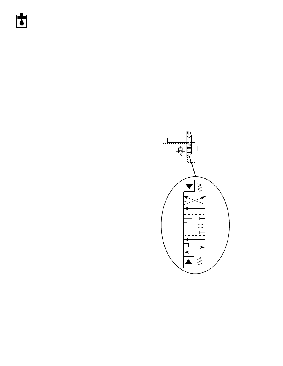
Figure 9– 17. Extend/retract spool valve schematic.
SHUTTLE IN
PILOT SELECT
MANIFOLD
PORT 12
LOAD SENSE
OUT
INLET
PILOT SELECT
MANIFOLD PORT 11
EXTEND/RETRACT
CYLINDER BASE END
EXTEND/RETRACT
CYLINDER ROD END
RESERVOIR
EXTEND
RETRACT
MS1910
C
B
A
F
E
D
C
B
A
F
E
D
C
B
A
F
E
D