SkyTrak 3606 Service Manual User Manual
Page 377
Electrical System
10-59
Model 3606 • Origin 10/99
Examine the fluid in the hydraulic oil sight glass
(Fig. 10– 61) to check whether there is a sufficient
amount of fluid in the system (the oil level should be at
the bottom of the sight glass with all hydraulic cylinders
retracted) and whether the fluid is contaminated. Replace
the hydraulic oil filter as required.
Figure 10– 61. Examine the fluid in the
hydraulic oil sight glass.
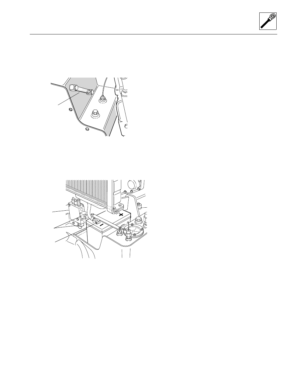
a. Hydraulic Oil Filter Pressure Switch Removal
1. Disconnect the negative (-) battery cable at the
negative battery terminal (Fig. 10– 62).
Figure 10– 62. Disconnect the negative (-) battery cable
at the negative (-) battery terminal.
2. Label and disconnect the hydraulic oil filter pressure
switch wiring connectors.
3. Unthread the switch from the hydraulic reservoir.
b. Disassembly
DO NOT disassemble the hydraulic oil filter pressure
switch. Replace a defective or faulty switch with a new
one.
c. Cleaning and Drying
DO NOT submerge the hydraulic oil filter pressure switch.
Clean only with an approved solvent and dry with a
clean, lint-free cloth.
d. Inspection and Replacement
Inspect switch wiring for continuity and shorting. Replace
a defective or faulty switch with a new one.
e. Installation and Testing
1. Thread the hydraulic oil filter pressure switch into its
welded fitting on the hydraulic reservoir. Tighten
securely.
2. Connect the switch wiring connector leads for the
wiring harness and for the hydraulic oil temperature
switch.
3. Connect the negative (-) battery cable to its battery
terminal (Fig. 10– 62).
4. Clear the area around the vehicle of personnel and
any obstructions to vehicle travel.
5. Start the engine, check for hydraulic fluid leaking at
the hydraulic oil filter pressure switch, and allow the
hydraulic fluid to reach operating temperature.
6. Cycle the boom several times and check whether the
hydraulic oil filter restriction indicator illuminates on
the operators display panel.
10.8.7 Hydraulic Oil Temperature Switch
The hydraulic oil temperature switch (Fig. 10– 60) is
threaded into a welded fitting at the top rear of the
hydraulic oil reservoir, inboard from the hydraulic oil filter
pressure switch. The hydraulic oil temperature switch is
connected to the hydraulic oil filter pressure switch, and
through it to the wiring harness and operators display
panel. When the hydraulic oil temperature is above
195° F (76° C), the hydraulic oil temperature warning
indicator on the operators display panel illuminates. The
vehicle should be stopped and the engine allowed to idle
at high idle for five minutes. If the warning indicator con-
tinues to illuminate after five minutes, the engine must be
shut down to help avoid damage in the hydraulic system.
Examine the fluid in the hydraulic oil sight glass (Fig. 10–
61) to check whether there is a sufficient amount of fluid
in the system (the oil level should be at the bottom of the
sight glass with all hydraulic cylinders retracted) and
whether the fluid is contaminated. Replace the hydraulic
oil filter as required. Explore other causes for excessive
temperature, such as high air temperature, plugged oil
cooler or lines, loose fan belt, plugged radiator, etc.
OS1590
Sight Glass
OS1040
Auxiliary
Function
Manifold
Park Brake
Solenoids
Negative (-)
Terminal