Transmission replacement, Transmission removal – SkyTrak 3606 Service Manual User Manual
Page 140
Section 7
7-6
7.5
TRANSMISSION REPLACEMENT
IMPORTANT: To help ensure safety and optimum per-
formance, replace the transmission if it is damaged.
Refer to the Sky Trak International Model 3606 Parts
Manual for ordering information.
Cleanliness is of extreme importance. Before attempting
to remove the transmission, thoroughly clean the exterior
of the transmission to help prevent dirt from entering dur-
ing the replacement process. Avoid spraying water or
cleaning solution onto or near the transmission shift sole-
noids and other electrical components.
7.5.1 Transmission Removal
1. Level the vehicle, ground the attachment, place the
travel select lever in Neutral (N), turn the wheels fully
to the left, and engage the parking brake switch.
2. Attach Accident Prevention Tags (see Section 1
Safety) to the ignition keyswitch and to the steering
wheel.
3. Unlock and open the engine compartment cover.
Allow the engine, transmission and hydraulic fluid to
cool.
4. Disconnect the battery negative (-) ground terminal to
help prevent the engine from starting accidentally.
5. Place a suitable receptacle under the transmission
drain plug (Fig. 7–4). Remove the transmission drain
plug and allow the transmission oil to drain into the
receptacle. Transfer the used transmission oil into a
suitable covered container and label the container as
used oil. Dispose of properly. Clean and reinstall the
transmission drain plug.
6. Disconnect the fuel run solenoid connection on the
top of the engine so the pump will not accidentally
operate, causing engine crankshaft rotation.
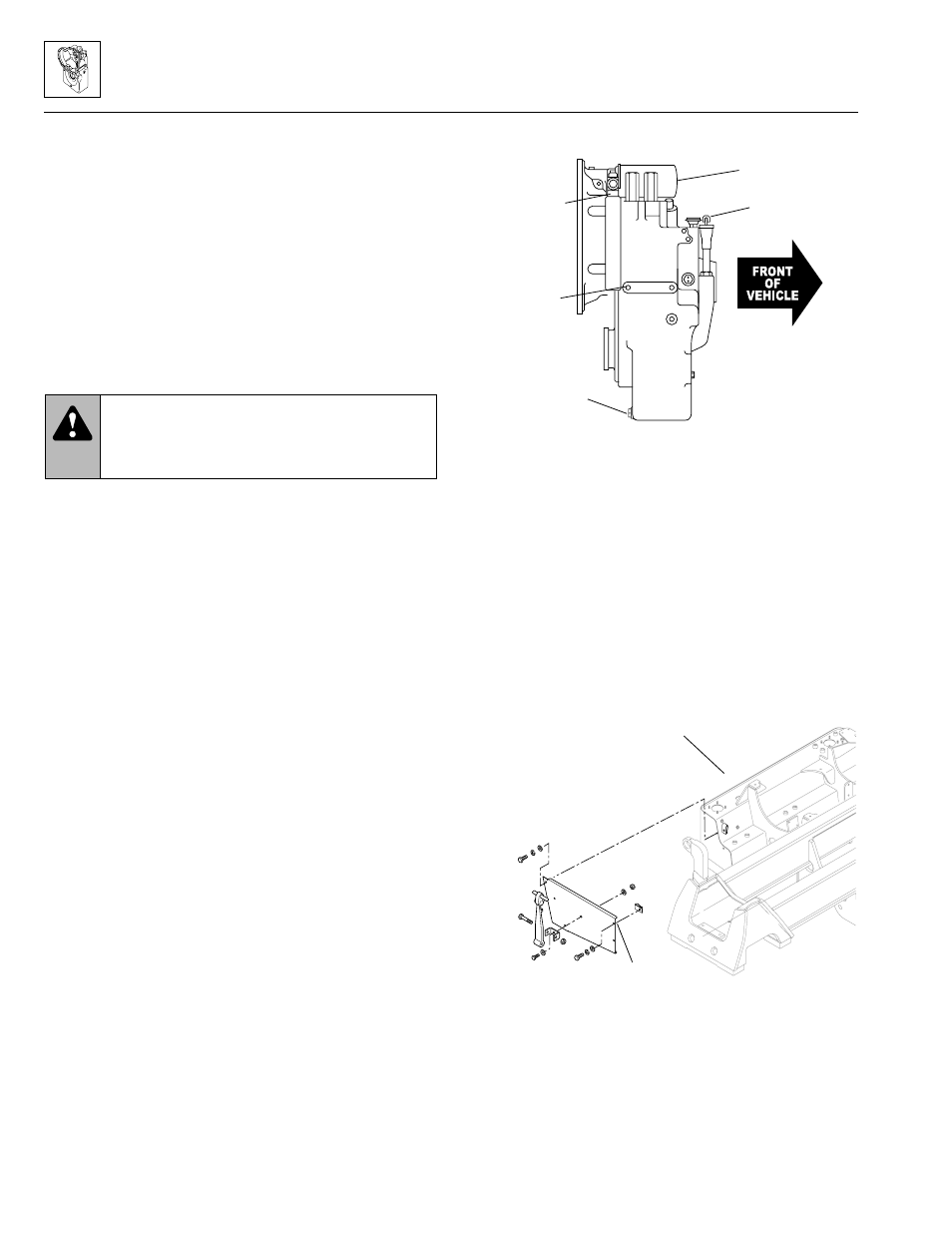
7. Remove the front engine cover plate (Fig. 7–5) from
the vehicle frame.
8. Remove the engine air cleaner assembly and the
bracket supporting the air cleaner inlet hose at the
turbocharger assembly on turbocharged engines.
Cover the air inlet to the turbo assembly on Cummins
engines. On Perkins naturally-aspirated engines,
cover the air intake.
9. Label, disconnect and cap the inlet and outlet hoses
at the main hydraulic pump, mounted to the
transmission.
Figure 7–4.
Place a suitable receptacle
under the transmission drain plug
.
10. Remove the main hydraulic pump from the
transmission.
11. Label, disconnect and cap the transmission oil cooler
inlet and outlet lines at the transmission. The
transmission oil cooler outlet hose (Fig. 7–3), routed
to the lower radiator fitting, is located on the right or
hydraulic reservoir side of the transmission. The
transmission oil cooler inlet hose, routed to the upper
radiator fitting, is located on the left or boom side of
the transmission, just below the position occupied by
the main hydraulic pump.
Figure 7–5. Engine front cover plate location.
12. Wipe up any spilled hydraulic and transmission oil.
13. Label and disconnect the transmission shift solenoid
wiring harness connectors. Move the wiring harness
safely out of the way.
WARNING: Risk of severe personal injury.
NEVER lift a transmission alone; enlist the help
of at least one assistant or use a suitable hoist
or overhead crane and sling.
•
Transmission
dipstick
Transmission
filter
Temperature
switch
Transmission
mount
bracket boss
Transmission
drain plug
OS1010
Frame (ref.)
Front engine
cover plate
MS0740
Model 3606 • Origin 10/99