Fuse and relay replacement -37 – SkyTrak 3606 Service Manual User Manual
Page 53
General Information, Specifications, and Maintenance
2-37
7. Next, remove the negative (-) jumper cable
connected to the negative (-) post of the booster
battery.
8. Remove the other end of the positive (+) jumper
cable connected to the positive (+) post of the
booster battery.
9. Remove the positive (+) jumper cable connected to
the positive (+) post of the discharged, but now
charging, battery.
10. Run the engine at partial throttle for 30 to 60 seconds
before attempting to operate the vehicle. Allow the
engine to return to idle RPM before engaging the
travel- or range-select levers.
2.12.16 Fuse and Relay Replacement
Note: There are three (3) types of fuse and relay panels
currently in use on the Sky Trak Model 3606. Vehicles
with serial number 8249 and before use the fuse and
relay panel shown in Fig. 2–68. Mid-production vehicles
with serial number 8250 through 9398 use the fuse and
relay panel shown in Fig. 2–69. Current production vehi-
cles with serial numbers 9399 and after use the fuse and
relay panel shown in Fig. 2–70.
IMPORTANT: Shut off the engine and disconnect the
negative battery cable before checking the electrical sys-
tem. Use an ohmmeter to check the resistance of wires
and components.
Fuses and relays help to protect the electrical system. In
general, a blown fuse is symptomatic of another electrical
problem. Simply replacing the fuse often will not solve the
problem. Blown fuses usually are due to simple causes,
including loose or corroded connections, or a defective
relay. The main causes of blown fuses include a shorted
or grounded wire in the applicable circuit, or a defective
electrical component. Visually check the condition of the
fuse, wires, connections and components in the involved
circuit before replacing a fuse. Check the circuit for
shorts, grounding or defective electrical components.
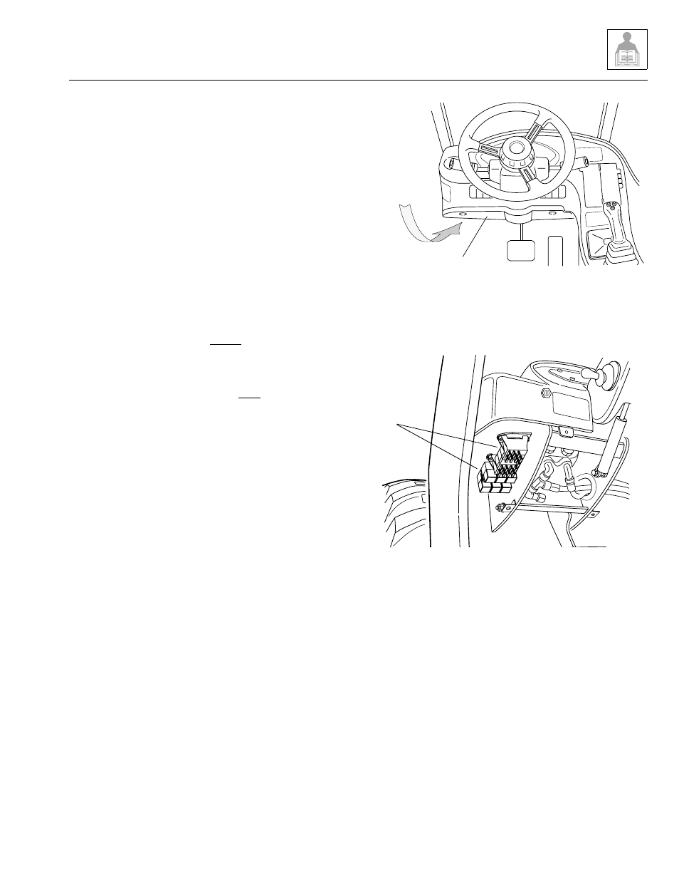
To gain access to the fuses and relays, remove the three
screws securing the lower dash panel to the cab (Fig. 2–
66). The fuses and relays are conveniently mounted
under the lower left side of the operator’s console (Fig. 2–
66). Remove the four screws securing the panel to gain
access to the fuses.
Figure 2–66. Remove the lower dash panel
to gain access to the fuses and relays.
Figure 2–67. Location of fuses and relays.
Before checking a malfunctioning electrical circuit, exam-
ine the applicable wiring diagram (see Section 10: Elec-
trical System) to help identify the components involved.
Problems can often be identified by noting whether other
components related to the circuit are functioning properly.
When several components or circuits fail at one time, the
problem is probably related to a poor ground connection,
because several circuits share that same connection.
See Section 10 Electrical System for further information.
Electrical
Fuse and
Relay Panel
Lower
Dash
Panel
OS1093
Fuse and
Relay Panel
OS1092
Model 3606 • Origin 10/99