Operator’s seat and seat belt – SkyTrak 3606 Service Manual User Manual
Page 95
Cab, Covers and Mirrors
4-9
20. Connect the battery negative (-) ground cable
21. Carefully examine all cab components, fasteners,
etc., one last time before engine start-up. Rectify any
faulty conditions.
22. Start the engine and check the operation of all
controls. Check for hydraulic fluid leaks. Check the
hydraulic fluid level in the tank and add fluid as
required.
4.2.3 Operator’s Seat and Seat Belt
Three types of operator’s seats are used. These include
the standard operator’s seat (Fig. 4–7), and two optional
seats that include a headrest and are covered in either
deluxe vinyl or deluxe cloth material and include head-
rests. The seat belt is attached to the seat assembly.
Figure 4–7. Seat styles include standard and optional.
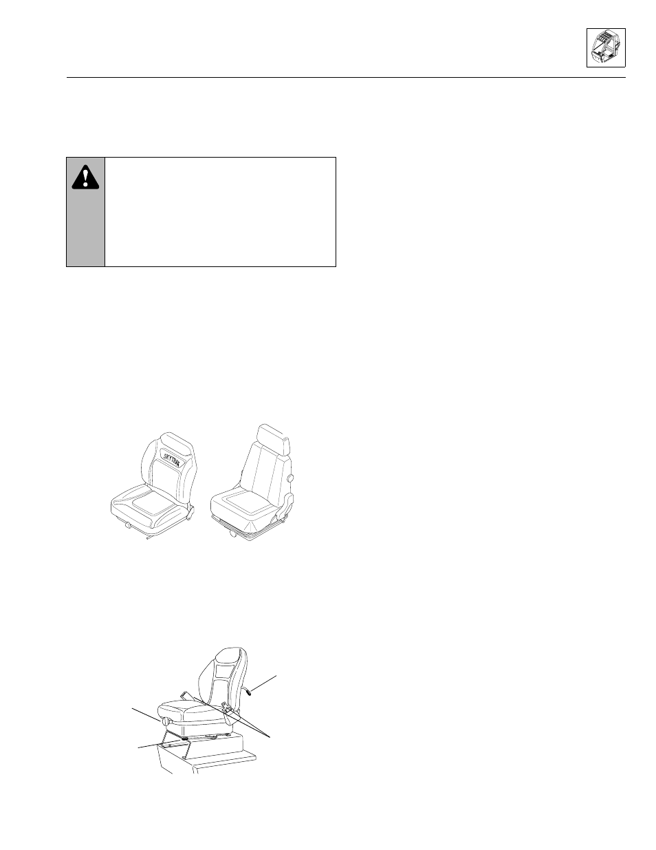
The seat assembly consists of upper (backrest) and
lower (bottom) cushions mounted on an adjustable sus-
pension unit (Fig. 4–8). Three seat adjustments can be
made: fore and aft position, suspension stiffness and
backrest angle. Seat adjustment information is contained
in the owners/operators manual.
Figure 4–8. Seat positions and stiffness can be adjusted.
An optional three-inch wide seat belt is available for
those locations that require a three-inch seat belt.
A. Seat Replacement
The seat can be removed from the cab by removing the
fasteners, including two tether cables, which secure the
seat to the cab. The seat belt is also easily removed by
removing the nuts, spacers, washers and capscrews
securing it to the seat frame. The seat tethers are
secured to the seat with the seat belt capscrews.
The seat and seat slides may be removed from the sus-
pension unit and mounting plate by removing four lock
nuts and flat washers that attach the seat slides to the
suspension unit.
Standard Seat Removal
Working from the outside rear of the cab, remove the rear
cab panel (item 3 in the General Overview illustration) to
gain access to the seat tether mounting hardware. The
rear cab panel is secured to the cab with 5/16-18 button-
head capscrews (4), 5/16" flat plastic washers (5) and
5/16-18 retaining nuts (6).
Note: Early production operator’s cabs included a
threaded hole for tether mounting. In Fig. 4–9, items 13
through 16 are not used on early production cabs.
1. Remove the 3/8-16 hex-lock elastic nuts
(16, Fig. 4–9) and rebound washers (15) securing the
tethers (2) to the rear of the cab.
Note: ALWAYS replace elastic-lined nuts with new
elastic-lined nuts to help ensure proper fastening.
2. Access to the right-side tether is restricted due to the
close proximity of the seat to the cab wall. Move the
seat all the way forward, and tip the seat back all the
way forward to gain access as needed to the tether
mounting hardware from inside the cab. If necessary,
remove the seat base mounting hardware before
removing the right-side tether.
Note: Early production operator’s cabs included a
threaded hole for tether mounting. In Fig. 4–9, items 13
through 16 are not used on early production cabs.
3. Remove four 5/16-18 hex-lock elastic nuts
(12, Fig. 4–9) and four 5/16 flat narrow washers
securing the seat (1) to the seat support (9).
Note: ALWAYS replace elastic-lined nuts with new
elastic-lined nuts to help ensure proper fastening.
4. Carefully remove the seat (Fig. 4–9) from the cab.
Remove the seat belt assembly and tethers (or
transfer these parts to the replacement seat) with the
seat out of the cab.
WARNING: DO NOT use your hand or any
part of your body to check for hydraulic leaks.
Hydraulic oil leaking under pressure can pene-
trate the skin and cause severe personal injury.
When checking for hydraulic leaks, wear safety
glasses and gloves to help provide protection
from spraying hydraulic oil. Use a piece of card-
board or paper to search for leaks.
MS0890
Standard
seat
Optional
seats
OS0200
Suspension
adjustment
knob
Fore & aft
adjustment
handle
Backrest angle
adjustment lever
Seat
belt
Model 3606 • Origin 10/99