Fig. 8a–12), Fig. 8a–12, Perkins engine – SkyTrak 3606 Service Manual User Manual
Page 163
Perkins Engine
8A-17
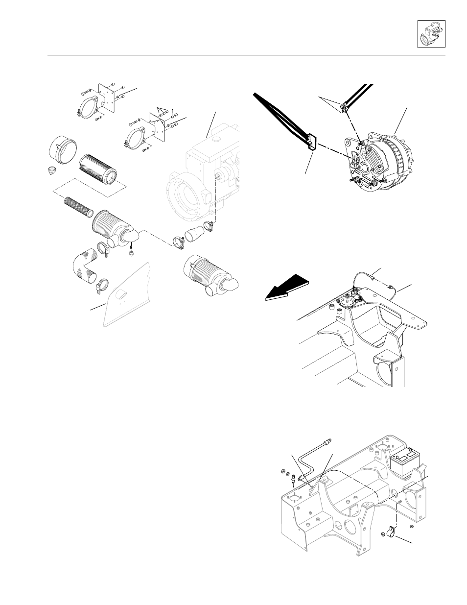
Figure 8A–12. Perkins air cleaner.
10. Disconnect the exhaust pipe (Fig. 8A–9) from the
exhaust bellows, secured with a heavy-duty T-bolt
band clamp. Cover the exhaust opening to help
prevent debris, etc. from entering.
11. Label and disconnect the alternator wire connector
(Fig. 8A–13) and both alternator ground wires.
Figure 8A–13. Label and disconnect the alternator wire
connector and both ground wires.
12. Disconnect (unplug) the hydraulic fluid level indicator
lead (Fig. 8A–10 and Fig. 8A–14) and the hydraulic
temperature sending unit lead (Fig. 8A–10) from the
wiring harness connector.
Figure 8A–14. Disconnect the hydraulic fluid
level indicator lead.
13. Label and disconnect the wires at the main ground
Figure 8A–15. Disconnect wires at the main ground stud.
1. Air cleaner assembly
(incl. items 2-6)
2.
Body assembly
3.
Safety filter
4.
Primary filter
5.
Cover assembly
6.
Vactuator valve
7. Heavy-duty T-bolt clamp
8. Air cleaner hose
9. Heavy-duty T-bolt clamp
10. Close nipple, #2
11. Vacuum switch
12. Hose clamp, SAE Type F
13. Air intake hose
14. Hex-head capscrew,
5/16-18 x 3/4"
15. Flat narrow washer, 5/16"
16. Air cleaner mount
band assembly
17. Hex-head capscrew,
M10-1,5 x 60 mm PC 8,8
(Natural only)
or
M10-1,5 x 60 mm PC 8,8
(Turbo only)
18. Lockwasher, M10
19. Air cleaner mount plate
20. Spacer, 0.40"
21. Spacer, 0.710"
22. Hex-lock elastic nut,
5/16-18
PS0480
Turbo mount
Natural mount
Engine (ref.)
Engine
panel (ref.)
MS1560
Ground
wires
Alternator
Wire connector
MS3020
Hydraulic fluid
level sending
unit lead
Engine
harness
lead
Front of
vehicle
MS1410
Ground
stud
Engine
mount
support
Tube clip
Model 3606 • Origin 10/99