Transmission maintenance, Maintenance introduction, Transmission maintenance schedule – SkyTrak 3606 Service Manual User Manual
Page 139
Transmission
7-5
7.4
TRANSMISSION MAINTENANCE
7.4.1 Maintenance Introduction
IMPORTANT: These instructions cover only the routine
maintenance of the transmission. Refer to the Clark-
Hurth T 12000 Powershift Transmission 3, 4, & 6 Speed
Intermediate Drop Maintenance and Service Manual,
part number SM T12-3,4,6 ID for information on trans-
mission diagnosis and internal component replacement.
Cleanliness is of extreme importance. Before attempting
any repairs, thoroughly clean the exterior of the transmis-
sion to help prevent dirt from entering while performing
maintenance checks and procedures.
Section 7.4.2 Transmission Maintenance Schedule pro-
vides a suggested maintenance schedule with refer-
ences to pertinent procedures and instructions in this
manual. To help prevent transmission problems before
they occur, follow the maintenance schedule.
Note: Lubrication and Maintenance Chart decals are
located inside the engine compartment cover (see
Fig. 7–2). These decals contain a general maintenance
schedule that should be followed to maintain the vehicle
in good operating condition (refer to Section 2 General
Information, Specifications and Maintenance Instruc-
tions). The same schedule information is presented in
Section 2.12.10 Transmission Oil and Filter with a
detailed account of how to perform the procedures.
7.4.2 Transmission Maintenance Schedule
Complete transmission maintenance information is
located in Section 2.12.10 Transmission Oil and Filter.
• At ten hour intervals, check the transmission oil level
(see Section 2.12.10 Transmission Oil and Filter).
• When the vehicle completes its first 50 hours of use,
change the transmission filter. Change the filter only;
DO NOT change the transmission oil and the filter at
the first 50 hour maintenance level (see Section
2.12.10 Transmission Oil and Filter).
• At 1,000 hour intervals, change the transmission oil
and filter (see Section 2.12.10 Transmission Oil and
Filter).
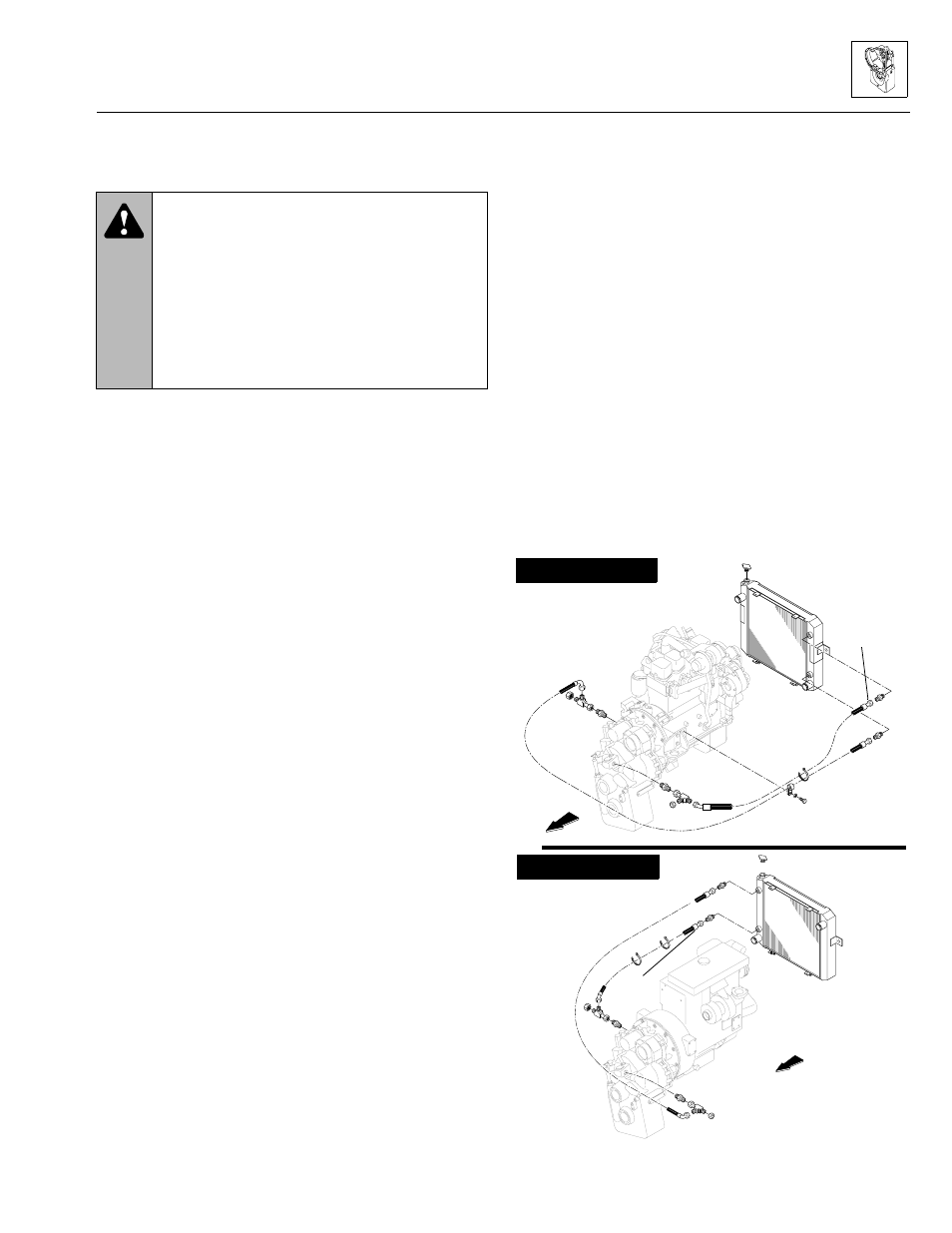
Periodically
Periodically, depending on operating conditions and other
factors, back flush the transmission oil cooler, which is
part of the radiator (Fig. 7–3). ALWAYS back flush the
transmission oil cooler after removing the transmission
for repair or replacement. The transmission oil cooler out-
let hose, routed to the lower radiator fitting, is located on
the right or hydraulic reservoir side of the transmission.
The transmission oil cooler inlet hose, routed to the
upper radiator fitting, is located on the left or boom side
of the transmission, just below the position occupied by
the main hydraulic pump (refer to Section 8A.5.3 Perkins
Engine Radiator and Oil Cooler Replacement, or to Sec-
tion 8B.5.3 Cummins Engine Radiator and Oil Cooler
Replacement for replacement procedures). Disconnect
and back flush the oil cooler portion of the radiator with
oil and compressed air until all foreign material is
removed. If necessary, remove the radiator from the vehi-
cle and clean the oil cooler circuit using oil, compressed
air and steam.
IMPORTANT: DO NOT use flushing compounds for
cleaning purposes.
Figure 7–3. Transmission oil cooler hose routings.
WARNING: To help avoid severe burns, DO
NOT attempt this procedure when the engine,
cooling, and hydraulic systems are hot. Wait
until they have cooled before proceeding.
• Exercise extreme care to help avoid skin
rashes, fire hazards and inhalation of harmful
vapors when using solvent and caustic
cleaners.
• Exercise extreme care when using a steam
cleaner to help avoid burns.
CUMMINS ENGINES
Outlet hose
Outlet
hose
Outlet
hose
Inlet
hose
Inlet
hose
Inlet
hose
Radiator
Radiator
Inlet
hose
PS0740
PS0750
PERKINS ENGINES
Model 3606 • Origin 10/99