Joystick circuit legend – SkyTrak 3606 Service Manual User Manual
Page 248
Section 9
9-54
9.8.8
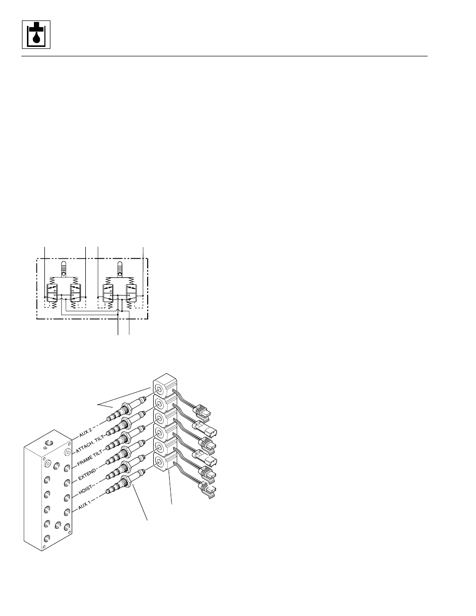
Joystick Circuit
Joystick hydraulic circuit (Fig. 9– 43) commands are
achieved through electric and hydraulic signals via a set
of cartridge-type, solenoid-operated control valves
mounted in an array at the pilot select manifold
(Fig. 9– 42).
The cartridge valves shift to allow hydraulic oil to flow to
the proper circuit as commanded by joystick position.
Hydraulic oil flows from the joystick valve to the pilot
select manifold (Fig. 9– 41), then to the appropriate
working section of the main control valve.
The valve plate assembly is provided in either standard
(Fig. 9– 44) or optional auxiliary hydraulics (Fig. 9– 45)
configurations. The valve plate assembly includes the
pilot select manifold and the main control valve.
Figure 9– 41. Joystick hydraulic circuit schematic.
Figure 9– 42. Pilot select manifold.
Joystick Circuit Legend
1. Joystick Valve
2. Connector, SAE 6 - Str. Thd. ORB x O-Ring Face Seal
3. Long Connector, SAE 6
4. Hose, 3/8” I.D. x 67”
5. Hose, 3/8” I.D. x 120-1/2”
6. Hose, 3/8” I.D. x 116”
7. Swivel Run Tee, SAE 6 - O-Ring Face Seal
8. Cap, SAE 6 - O-Ring Face Seal
9. Branch Tee, SAE 6 - Str. Thd. ORB x O-Ring Face Seal
10. 90° Elbow, SAE 6 - Str. Thd. ORB x O-Ring Face Seal
11. 90° Elbow, SAE 6-8 - Str. Thd. ORB x O-Ring Face Seal
JOYSTICK
TO PILOT SELECT MANIFOLD
INPUT
RESERVOIR
RIGHT
2
4
LEFT
T
P
3
1
FWD. BACK
MS1980
Optional Aux.
Hydraulics ONLY
Solenoid Coil
Cartridge Valve
Pilot Select
Manifold
MS1990
Model 3606 • Origin 10/99