Frame tilt circuit -32 – SkyTrak 3606 Service Manual User Manual
Page 226
Section 9
9-32
Model 3606 • Origin 10/99
9.8.4
Frame Tilt Circuit
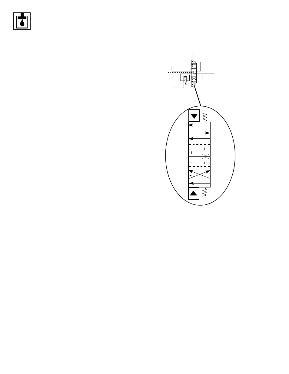
a. Frame Tilt LEFT
With the two frame tilt select buttons on the joystick
depressed and held, and the joystick moved to the left,
the spool valve in the frame tilt directional control valve
(Fig. 9– 21) of the main control valve assembly (see
Fig. 9– 22) is shifted by pilot pressure. System pressure is
directed to ports A-D (Fig. 9– 21), then B-F of the spool
valve (in the main control valve), and from there to the
base end of the frame tilt cylinder. Oil from the rod end of
the frame tilt cylinder flows through a check valve,
unseated by system pressure, to the stabilizer cylinder,
through the solenoid valve, back to the spool valve
through ports E-C to the return filter and the reservoir.
b. Frame Tilt RIGHT
With the two frame tilt select buttons on the joystick
depressed and held, and the joystick moved to the right,
the spool valve in the frame tilt directional control valve of
the main control valve assembly is shifted by pilot pres-
sure.
System pressure is directed to ports D-A then B-E of the
spool valve (Fig. 9– 21), then to the stabilizer cylinder,
through the solenoid valve, back to the frame tilt cylinder,
where it flows to the rod end of the cylinder. Oil from the
base end of the cylinder flows through the check valve,
which was unseated by system pressure, then to ports
F-C of the spool valve, to the return filter and the
hydraulic fluid reservoir.
Figure 9– 21. Frame tilt spool valve circuit schematic.
SHUTTLE IN
PILOT SELECT
MANIFOLD
PORT 9
LOAD SENSE
OUT
INLET
PILOT SELECT
MANIFOLD PORT 10
STABIL-TRAK
MANIFOLD PORT “V”
FRAME TILT CYLINDER
PORT “FTB”
RESERVOIR
2 GPM
MAX
MS1920
C
B
A
F
E
D
C
B
A
F
E
D
C
B
A
F
E
D