SkyTrak 3606 Service Manual User Manual
Page 400
Section 10
10-82
Model 3606 • Origin 10/99
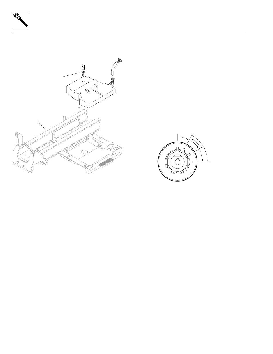
The fuel level sender (Fig. 10– 107) consists of a resis-
tance, float-type fuel level sender mounted in the top of
the fuel tank, and the wiring connecting it with the fuel
indicators in the operators display panel.
Figure 10– 107. Fuel level sender.
The resistance of the fuel sender is 33.5 ohms for a full
tank of fuel and 240 ohms for an empty tank. The fuel
level indicator bars in the operators display panel receive
a signal sensed within the electronic circuitry of the oper-
ators display panel. Examine the fuel level sender circuit
in the appropriate wiring diagram and schematic earlier
in this section.
Battery voltage is applied to the circuit and the circuit
divides at the fuel level indicator bars. One path contin-
ues to ground through the operators display panel and
fuel level indicator connector plug. Another electrical path
goes to ground through the variable resistor of the fuel
level sender.
When the fuel level reaches approximately 1/8 of a tank,
the resistance of the sender increases. This in turn
changes the operators display panel, causing the green
fuel level indicator bars to turn OFF, and resulting in the
orange fuel indicator symbol (shaped like a standard fuel
pump) to turn ON.
When the tank is more than 1/8 full, the sender resis-
tance is lower. On the operators display panel, the green
fuel level indicator bars illuminate according to the
amount of resistance supplied.
a. Fuel Level Indicator Testing
1. With approximately eight gallons (30,4 liters) of fuel
in the fuel tank (Fig. 10– 107), the bottom fuel level
indicator bar should illuminate, indicating
approximately 1/4 tank of fuel.
2. The fuel level sender wiring harness connector can
be accessed from beneath the cab without removing
the cab. Beneath the cab, disconnect the fuel level
sender wiring harness connector. Connect a jumper
wire across the two wires in the harness connector.
3. From the operators position, turn the ignition key
switch to the RUN position (Fig. 10– 108). DO NOT
start the engine. Observe the fuel level indicator bars
on the operators display panel. The reading must be
at the FULL mark, with all four bars illuminated after
the engine start-up bulb test is completed.
Figure 10– 108. Ignition key switch positions.
4. Turn the ignition key switch to the OFF position. The
bars should turn OFF.
The cab must be partially removed to access the fuel
tank and fuel sender. See Section 4 Cab, Covers and
Mirrors in this manual for cab and fuel tank removal
instructions.
b. Fuel Level Circuit Tests
If the fuel level indicators are suspected of giving a false
reading, perform the following checks:
1. Check for loose or defective wiring, faulty ground
connections, and corrosion on the fuel tank sender
and wiring lead.
2. If the fuel level indicator bars do not illuminate after
the engine start-up bulb test is completed and when
the ignition key switch is turned to the RUN position,
use a test lamp to determine whether current is
flowing from the ignition switch to the fuel level
indicator wiring connector behind the operators
display panel (the panel can be unfastened and
raised slightly to do this).
3. If the fuel level indicator bars do not illuminate, check
the fuel tank for fuel.
MS1790
Fuel Level
Sender
Fuel Tank
Vehicle Frame (ref.)
OF0390
OFF
RUN
PREHEAT
START